nd120_cmod_top
Source: Verilog/fpga/cmod-a7-35t/nd120_cmod_top.v
Where it sits (Cmod): nd120_cmod_top
Used in: nothing - this is a top (Cmod).
Contains: ND120_TOP
Module hierarchy - All modules
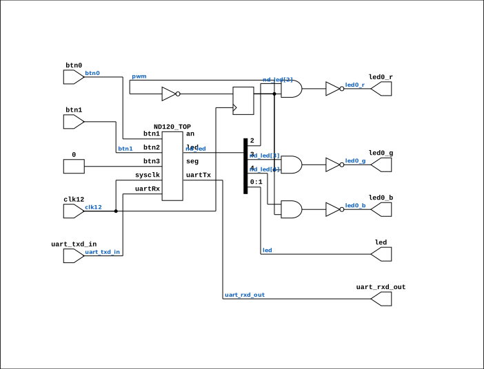
Schematic
Drawn from the Verilog: the yosys netlist of the Cmod A7-35T build, where it is the top. Sub-modules are boxes (click the picture to open it full size; there every sub-module box links to its page, and every wire shows its Verilog name).
Description
Cmod A7-35T wrapper for the ND-120 CPU (ND120_TOP, BRAM main memory) First-version bring-up build: same shape as the Basys3 build (FPGA_FF_MODE + MAIN_RAM_BLOCKRAM + runtime WCS load from the PROM images), but clocked at 27 MHz - the Tang Nano 20K's full CPU speed - via the TARGET_CMOD_A7 MMCM branch in ND120_TOP.v (12 MHz x 63 / 28 = 27.000 MHz exactly; BOARD_CLK_FREQ=27000000 keeps every derived count honest). The wrapper only adapts the board I/O: the Cmod has 2 buttons, 2 LEDs + 1 RGB LED, no switches, no 7-segment display. ND120_TOP's seg/an outputs are left unconnected and its 16-bit LED bus is condensed to what the board has. Build: vivado -mode batch -source build.tcl (see README.md) Last reviewed: 13-JUL-2026 Ronny Hansen
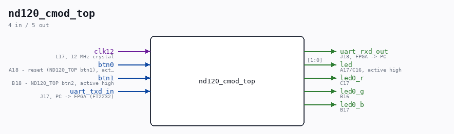
Ports
| Direction | Width | Name | Description |
|---|---|---|---|
| input | 1 |
clk12 |
L17, 12 MHz crystal |
| input | 1 |
btn0 |
A18 - reset (ND120_TOP btn1), active high |
| input | 1 |
btn1 |
B18 - ND120_TOP btn2, active high |
| input | 1 |
uart_txd_in |
J17, PC -> FPGA (FT2232) |
| output | 1 |
uart_rxd_out |
J18, FPGA -> PC |
| output | [1:0] |
led |
A17/C16, active high |
| output | 1 |
led0_r |
C17 |
| output | 1 |
led0_g |
B16 |
| output | 1 |
led0_b |
B17 |
Verilog source
Verilog/fpga/cmod-a7-35t/nd120_cmod_top.v on GitHub.
Show the Verilog of nd120_cmod_top (73 lines)
/****************************************************************************
** Cmod A7-35T wrapper for the ND-120 CPU (ND120_TOP, BRAM main memory)    **
**                                                                         **
** First-version bring-up build: same shape as the Basys3 build            **
** (FPGA_FF_MODE + MAIN_RAM_BLOCKRAM + runtime WCS load from the PROM      **
** images), but clocked at 27 MHz - the Tang Nano 20K's full CPU speed -   **
** via the TARGET_CMOD_A7 MMCM branch in ND120_TOP.v (12 MHz x 63 / 28 =   **
** 27.000 MHz exactly; BOARD_CLK_FREQ=27000000 keeps every derived count   **
** honest).                                                                **
**                                                                         **
** The wrapper only adapts the board I/O: the Cmod has 2 buttons, 2 LEDs   **
** + 1 RGB LED, no switches, no 7-segment display. ND120_TOP's seg/an     **
** outputs are left unconnected and its 16-bit LED bus is condensed to     **
** what the board has.                                                     **
**                                                                         **
** Build: vivado -mode batch -source build.tcl   (see README.md)          **
**                                                                         **
** Last reviewed: 13-JUL-2026                                              **
** Ronny Hansen                                                            **
*****************************************************************************/

module nd120_cmod_top (
    input clk12,  // L17, 12 MHz crystal

    input btn0,  // A18 - reset (ND120_TOP btn1), active high
    input btn1,  // B18 - ND120_TOP btn2, active high

    input  uart_txd_in,   // J17, PC -> FPGA (FT2232)
    output uart_rxd_out,  // J18, FPGA -> PC

    output [1:0] led,  // A17/C16, active high

    // RGB LED - ACTIVE LOW (reference manual), and the manual warns never
    // to drive a color steadily (uncomfortably bright): PWM <= 50% duty.
    // Gated with a 50% divided clock below.
    output led0_r,  // C17
    output led0_g,  // B16
    output led0_b   // B17
);

  // ND120_TOP's Basys3-shaped outputs, condensed for this board
  wire [15:0] nd_led;
  /* verilator lint_off UNUSEDSIGNAL */
  wire [ 6:0] nd_seg;  // no 7-segment display on the Cmod
  wire [ 3:0] nd_an;
  /* verilator lint_on UNUSEDSIGNAL */

  // Basys3 LED map (ND120_TOP.v): 0=CPU RED (error/halt), 1=CPU GREEN
  // (running), 2=RUN indicator, 3=sys_rst_n state, 4=UART TX activity
  assign led[0] = nd_led[0];  // error/halt
  assign led[1] = nd_led[1];  // running

  // RGB at 50% duty (active low: 0 = lit half the time, 1 = dark)
  reg pwm = 1'b0;
  always @(posedge clk12) pwm <= ~pwm;

  assign led0_r = ~(nd_led[2] & pwm);  // RUN indicator (lit = NOT running/OPCOM)
  assign led0_g = ~(nd_led[3] & pwm);  // reset released
  assign led0_b = ~(nd_led[4] & pwm);  // UART TX activity

  ND120_TOP nd120 (
      .sysclk(clk12),
      .btn1  (btn0),        // reset
      .btn2  (btn1),
      .btn3  (1'b0),        // unused (fixed clk_cpu)
      .uartRx(uart_txd_in),
      .uartTx(uart_rxd_out),
      .led   (nd_led),
      .seg   (nd_seg),
      .an    (nd_an)
  );

endmodule