board_test_top
Source: Verilog/fpga/nexys4ddr/board-test/board_test_top.v
Hierarchy: not instantiated by any of the 9 build tops (elaborated by yosys).
Module hierarchy - All modules
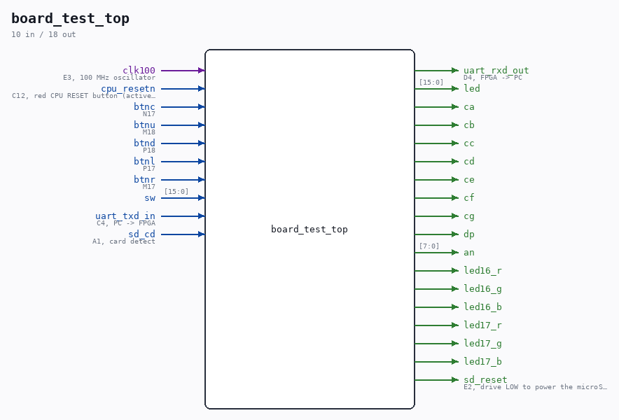
Schematic
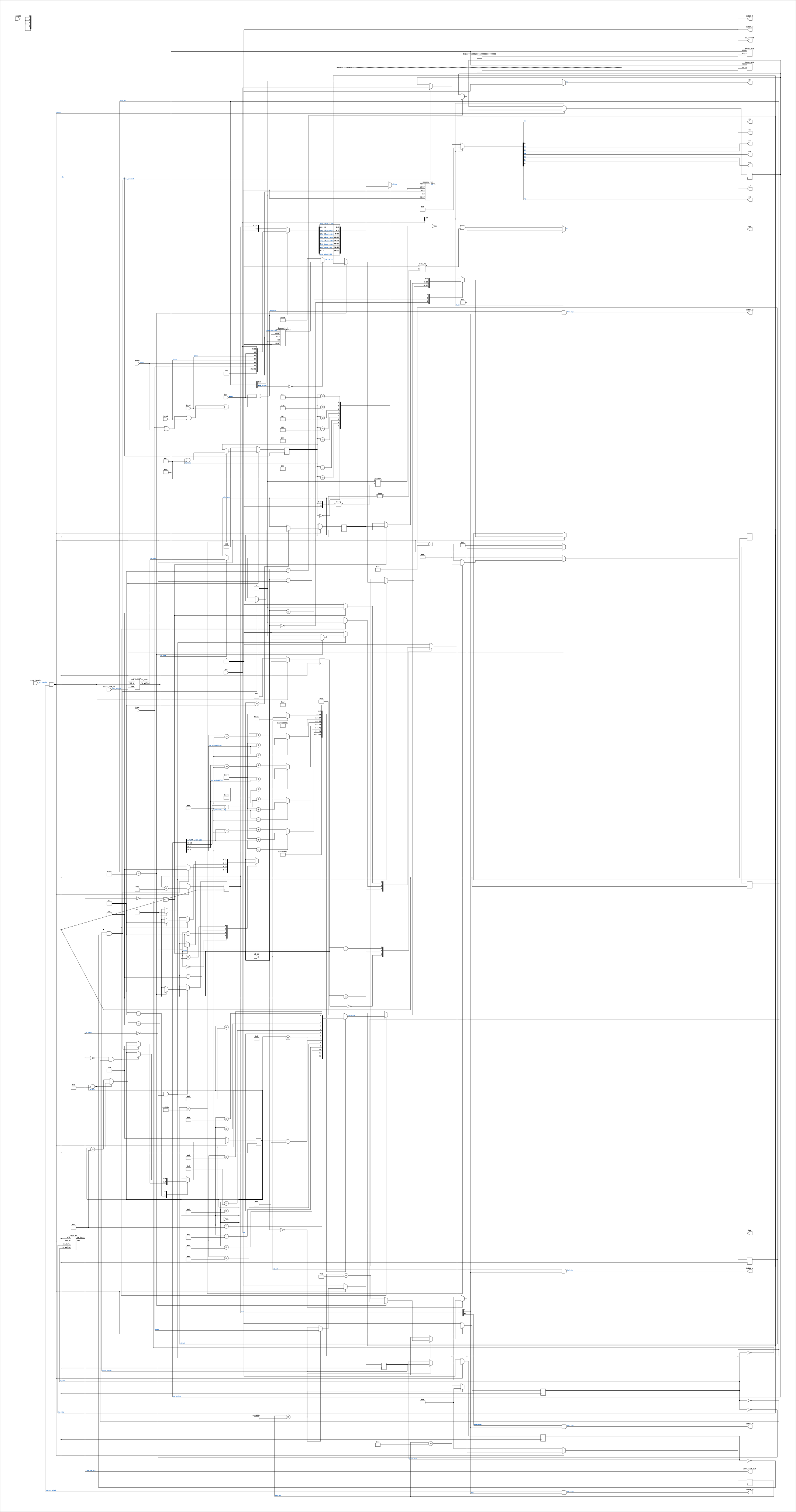
Drawn from the Verilog: no build top uses this module, so it was elaborated from its own file with no defines and default parameters. Sub-modules are boxes (click the picture to open it full size; there every sub-module box links to its page, and every wire shows its Verilog name).
Description
Nexys 4 DDR board check - proves the parts the ND-120 build depends on This is a BRING-UP test, not an ND-120 build. It exercises exactly the board resources fpga/nexys4ddr/build.tcl relies on, so a failure here is a board or toolchain problem, never a CPU problem: - the 100 MHz oscillator and the MMCM that makes clk_cpu (the same VCO 1000 MHz / 60 = 16.667 MHz the ND-120 build uses by default) - all 16 slide switches -> all 16 LEDs - all 8 seven-segment digits and all 7 segments + decimal point - the five buttons and the active-low CPU RESET button - the USB-UART at 9600 8N1, both directions - the ND-120 console - the microSD slot power gate and card-detect switch - the two RGB LEDs (status) What it does NOT test: DDR2, VGA, Ethernet, accelerometer, microphone, audio, USB-HID. The factory demo in the QSPI flash covers those - see README.md, and run that FIRST. Last reviewed: 20-AUG-2026 Ronny Hansen
Ports
| Direction | Width | Name | Description |
|---|---|---|---|
| input | 1 |
clk100 |
E3, 100 MHz oscillator |
| input | 1 |
cpu_resetn |
C12, red CPU RESET button (active low) |
| input | 1 |
btnc |
N17 |
| input | 1 |
btnu |
M18 |
| input | 1 |
btnd |
P18 |
| input | 1 |
btnl |
P17 |
| input | 1 |
btnr |
M17 |
| input | [15:0] |
sw |
|
| input | 1 |
uart_txd_in |
C4, PC -> FPGA |
| output | 1 |
uart_rxd_out |
D4, FPGA -> PC |
| output | [15:0] |
led |
|
| output | 1 |
ca |
|
| output | 1 |
cb |
|
| output | 1 |
cc |
|
| output | 1 |
cd |
|
| output | 1 |
ce |
|
| output | 1 |
cf |
|
| output | 1 |
cg |
|
| output | 1 |
dp |
|
| output | [7:0] |
an |
|
| output | 1 |
led16_r |
|
| output | 1 |
led16_g |
|
| output | 1 |
led16_b |
|
| output | 1 |
led17_r |
|
| output | 1 |
led17_g |
|
| output | 1 |
led17_b |
|
| output | 1 |
sd_reset |
E2, drive LOW to power the microSD slot |
| input | 1 |
sd_cd |
A1, card detect |
Verilog source
Verilog/fpga/nexys4ddr/board-test/board_test_top.v on GitHub.
Show the Verilog of board_test_top (439 lines)
/****************************************************************************
** Nexys 4 DDR board check - proves the parts the ND-120 build depends on  **
**                                                                         **
** This is a BRING-UP test, not an ND-120 build. It exercises exactly the  **
** board resources fpga/nexys4ddr/build.tcl relies on, so a failure here   **
** is a board or toolchain problem, never a CPU problem:                   **
**                                                                         **
**   - the 100 MHz oscillator and the MMCM that makes clk_cpu (the same    **
**     VCO 1000 MHz / 60 = 16.667 MHz the ND-120 build uses by default)    **
**   - all 16 slide switches -> all 16 LEDs                                **
**   - all 8 seven-segment digits and all 7 segments + decimal point       **
**   - the five buttons and the active-low CPU RESET button                **
**   - the USB-UART at 9600 8N1, both directions - the ND-120 console      **
**   - the microSD slot power gate and card-detect switch                  **
**   - the two RGB LEDs (status)                                           **
**                                                                         **
** What it does NOT test: DDR2, VGA, Ethernet, accelerometer, microphone,  **
** audio, USB-HID. The factory demo in the QSPI flash covers those - see   **
** README.md, and run that FIRST.                                          **
**                                                                         **
** Last reviewed: 20-AUG-2026                                              **
** Ronny Hansen                                                            **
*****************************************************************************/

module board_test_top (
    input clk100,  // E3, 100 MHz oscillator

    input cpu_resetn,  // C12, red CPU RESET button (active low)
    input btnc,        // N17
    input btnu,        // M18
    input btnd,        // P18
    input btnl,        // P17
    input btnr,        // M17

    input [15:0] sw,

    input  uart_txd_in,   // C4, PC -> FPGA
    output uart_rxd_out,  // D4, FPGA -> PC

    output [15:0] led,

    output       ca,
    output       cb,
    output       cc,
    output       cd,
    output       ce,
    output       cf,
    output       cg,
    output       dp,
    output [7:0] an,

    output led16_r,
    output led16_g,
    output led16_b,
    output led17_r,
    output led17_g,
    output led17_b,

    output sd_reset,  // E2, drive LOW to power the microSD slot
    input  sd_cd      // A1, card detect
);

  localparam CLK_HZ = 16_666_667;  // MMCM output below
  localparam BAUD = 9600;
  localparam DELAY_FRAMES = CLK_HZ / BAUD;  // 1736

  // ---------------------------------------------------------------------
  // Clock: the SAME MMCM shape the ND-120 build uses (VCO 1000 MHz / 60).
  // If this does not lock, nothing about the ND-120 clock plan is testable.
  // ---------------------------------------------------------------------
  wire clk_pre, clkfb_out, clkfb_in, mmcm_locked, clk;

  MMCME2_BASE #(
      .BANDWIDTH("OPTIMIZED"),
      .CLKFBOUT_MULT_F(10.0),    // VCO = 100 * 10 = 1000 MHz
      .CLKIN1_PERIOD(10.0),      // 100 MHz input
      .CLKOUT0_DIVIDE_F(60.0),   // 1000 / 60 = 16.667 MHz
      .DIVCLK_DIVIDE(1),
      .STARTUP_WAIT("FALSE")
  ) mmcm (
      .CLKIN1  (clk100),
      .CLKFBIN (clkfb_in),
      .CLKFBOUT(clkfb_out),
      .CLKOUT0 (clk_pre),
      .LOCKED  (mmcm_locked),
      .PWRDWN  (1'b0),
      .RST     (1'b0)
  );
  BUFG bufg_fb (.I(clkfb_out), .O(clkfb_in));
  BUFG bufg_clk(.I(clk_pre),   .O(clk));

  // Reset: CPU RESET button (active low) qualified by MMCM lock
  wire rst_n = cpu_resetn & mmcm_locked;

  // ---------------------------------------------------------------------
  // Heartbeat / free-running counter
  // ---------------------------------------------------------------------
  reg [31:0] ticks = 32'd0;
  always @(posedge clk) begin
    if (!rst_n) ticks <= 32'd0;
    else ticks <= ticks + 32'd1;
  end
  wire heartbeat = ticks[23];  // ~1 Hz at 16.667 MHz

  // ---------------------------------------------------------------------
  // Switches -> LEDs (the factory demo's behaviour, so the comparison with
  // the out-of-box test is direct)
  // ---------------------------------------------------------------------
  assign led = sw;

  // ---------------------------------------------------------------------
  // RGB LEDs: status. Active HIGH on this board; keep the duty low so they
  // are not painfully bright (the same courtesy the Cmod wrapper applies).
  // LED16: green = MMCM locked, red = the SD_CD line is high. The polarity of
  //        SD_CD (high or low with a card inserted) is NOT stated in the
  //        reference manual text, so this indicator is deliberately labelled
  //        as "the CD line", not "card present" - insert and remove a card
  //        while watching it, and that settles the polarity.
  // LED17: blue = heartbeat, green = a button is pressed
  // ---------------------------------------------------------------------
  wire dim = ticks[4];  // ~6% duty at this ratio of the counter
  wire any_btn = btnc | btnu | btnd | btnl | btnr;

  assign led16_g = mmcm_locked & dim;
  assign led16_r = sd_cd & dim;
  assign led16_b = 1'b0;
  assign led17_b = heartbeat & dim;
  assign led17_g = any_btn & dim;
  assign led17_r = 1'b0;

  // microSD slot power gate: low = powered (reference manual section 12)
  assign sd_reset = 1'b0;

  // ---------------------------------------------------------------------
  // Seven-segment display: EIGHT digits.
  //   sw[15] = 0 : 32-bit counter in hex - every digit changes, so a dead
  //                digit or a dead segment shows up immediately
  //   sw[15] = 1 : every segment of every digit lit, decimal points too -
  //                the direct test for a broken segment
  // Buttons override the value so the button wiring is visible on the
  // display as well as on the RGB LED.
  // ---------------------------------------------------------------------
  wire [31:0] disp_value = any_btn
      ? {12'h0, btnc, btnu, btnd, btnl, btnr, sw[15:0]}
      : ticks[31:0];

  reg [2:0] digit_sel = 3'd0;
  reg [16:0] refresh = 17'd0;
  always @(posedge clk) begin
    if (!rst_n) begin
      refresh   <= 17'd0;
      digit_sel <= 3'd0;
    end else if (refresh == 17'd16_666) begin  // ~1 kHz per digit
      refresh   <= 17'd0;
      digit_sel <= digit_sel + 3'd1;
    end else begin
      refresh <= refresh + 17'd1;
    end
  end

  reg [3:0] nibble;
  always @(*) begin
    case (digit_sel)
      3'd0: nibble = disp_value[3:0];
      3'd1: nibble = disp_value[7:4];
      3'd2: nibble = disp_value[11:8];
      3'd3: nibble = disp_value[15:12];
      3'd4: nibble = disp_value[19:16];
      3'd5: nibble = disp_value[23:20];
      3'd6: nibble = disp_value[27:24];
      3'd7: nibble = disp_value[31:28];
    endcase
  end

  // seg[6:0] = gfedcba, active LOW (same encoding as Shared/support/SevenSegDebug.v)
  reg [6:0] seg;
  always @(*) begin
    case (nibble)
      4'h0: seg = 7'b1000000;
      4'h1: seg = 7'b1111001;
      4'h2: seg = 7'b0100100;
      4'h3: seg = 7'b0110000;
      4'h4: seg = 7'b0011001;
      4'h5: seg = 7'b0010010;
      4'h6: seg = 7'b0000010;
      4'h7: seg = 7'b1111000;
      4'h8: seg = 7'b0000000;
      4'h9: seg = 7'b0010000;
      4'hA: seg = 7'b0001000;
      4'hB: seg = 7'b0000011;
      4'hC: seg = 7'b1000110;
      4'hD: seg = 7'b0100001;
      4'hE: seg = 7'b0000110;
      4'hF: seg = 7'b0001110;
    endcase
  end

  wire all_on = sw[15];
  assign {cg, cf, ce, cd, cc, cb, ca} = all_on ? 7'b0000000 : seg;
  assign dp = all_on ? 1'b0 : 1'b1;  // active low

  reg [7:0] an_r;
  always @(*) begin
    an_r = 8'hFF;                 // all off (active low)
    if (all_on) an_r = 8'h00;     // all digits on
    else an_r[digit_sel] = 1'b0;  // one digit at a time
  end
  assign an = an_r;

  // ---------------------------------------------------------------------
  // Button debounce (~10 ms) and rising-edge detection for BTNC
  // ---------------------------------------------------------------------
  reg [17:0] deb_cnt = 18'd0;
  reg btnc_stable = 1'b0, btnc_prev = 1'b0;
  always @(posedge clk) begin
    if (!rst_n) begin
      deb_cnt     <= 18'd0;
      btnc_stable <= 1'b0;
      btnc_prev   <= 1'b0;
    end else begin
      if (deb_cnt == 18'd166_666) begin  // 10 ms
        deb_cnt     <= 18'd0;
        btnc_prev   <= btnc_stable;
        btnc_stable <= btnc;
      end else begin
        deb_cnt <= deb_cnt + 18'd1;
      end
    end
  end
  wire btnc_pressed = btnc_stable & ~btnc_prev;

  // ---------------------------------------------------------------------
  // UART: banner on reset, echo of every received byte, and a switch report
  // on BTNC. This is the ND-120's console path, at the ND-120's baud rate.
  // ---------------------------------------------------------------------
  wire [7:0] rx_data;
  wire       rx_valid;
  reg  [7:0] tx_data;
  reg        tx_valid;
  wire       tx_busy;

  uart_rx #(.DELAY_FRAMES(DELAY_FRAMES)) RX (
      .clk(clk), .rst_n(rst_n), .rxd(uart_txd_in),
      .rx_data(rx_data), .rx_valid(rx_valid)
  );
  uart_tx #(.DELAY_FRAMES(DELAY_FRAMES)) TX (
      .clk(clk), .rst_n(rst_n),
      .tx_data(tx_data), .tx_valid(tx_valid), .tx_busy(tx_busy),
      .txd(uart_rxd_out)
  );

  // State registers (declared before the combinational ROMs that read them)
  reg [8:0]  msg_idx;
  reg [3:0]  rep_idx;
  reg [15:0] sw_latched;

  // Banner ROM. Kept short on purpose - it is a wiring test, not a manual.
  localparam BANNER_LEN = 9'd85;
  reg [7:0] banner_ch;
  always @(*) begin
    case (msg_idx)
      9'd0:  banner_ch = 8'h0D;
      9'd1:  banner_ch = 8'h0A;
      9'd2:  banner_ch = "N";
      9'd3:  banner_ch = "E";
      9'd4:  banner_ch = "X";
      9'd5:  banner_ch = "Y";
      9'd6:  banner_ch = "S";
      9'd7:  banner_ch = "4";
      9'd8:  banner_ch = "D";
      9'd9:  banner_ch = "D";
      9'd10: banner_ch = "R";
      9'd11: banner_ch = " ";
      9'd12: banner_ch = "B";
      9'd13: banner_ch = "O";
      9'd14: banner_ch = "A";
      9'd15: banner_ch = "R";
      9'd16: banner_ch = "D";
      9'd17: banner_ch = " ";
      9'd18: banner_ch = "C";
      9'd19: banner_ch = "H";
      9'd20: banner_ch = "E";
      9'd21: banner_ch = "C";
      9'd22: banner_ch = "K";
      9'd23: banner_ch = 8'h0D;
      9'd24: banner_ch = 8'h0A;
      9'd25: banner_ch = "M";
      9'd26: banner_ch = "M";
      9'd27: banner_ch = "C";
      9'd28: banner_ch = "M";
      9'd29: banner_ch = " ";
      9'd30: banner_ch = "1";
      9'd31: banner_ch = "6";
      9'd32: banner_ch = ".";
      9'd33: banner_ch = "6";
      9'd34: banner_ch = "6";
      9'd35: banner_ch = "7";
      9'd36: banner_ch = "M";
      9'd37: banner_ch = "H";
      9'd38: banner_ch = "z";
      9'd39: banner_ch = " ";
      9'd40: banner_ch = "L";
      9'd41: banner_ch = "O";
      9'd42: banner_ch = "C";
      9'd43: banner_ch = "K";
      9'd44: banner_ch = "E";
      9'd45: banner_ch = "D";
      9'd46: banner_ch = 8'h0D;
      9'd47: banner_ch = 8'h0A;
      9'd48: banner_ch = "T";
      9'd49: banner_ch = "y";
      9'd50: banner_ch = "p";
      9'd51: banner_ch = "e";
      9'd52: banner_ch = " ";
      9'd53: banner_ch = "-";
      9'd54: banner_ch = " ";
      9'd55: banner_ch = "c";
      9'd56: banner_ch = "h";
      9'd57: banner_ch = "a";
      9'd58: banner_ch = "r";
      9'd59: banner_ch = "s";
      9'd60: banner_ch = " ";
      9'd61: banner_ch = "e";
      9'd62: banner_ch = "c";
      9'd63: banner_ch = "h";
      9'd64: banner_ch = "o";
      9'd65: banner_ch = ".";
      9'd66: banner_ch = " ";
      9'd67: banner_ch = "B";
      9'd68: banner_ch = "T";
      9'd69: banner_ch = "N";
      9'd70: banner_ch = "C";
      9'd71: banner_ch = " ";
      9'd72: banner_ch = "=";
      9'd73: banner_ch = " ";
      9'd74: banner_ch = "s";
      9'd75: banner_ch = "w";
      9'd76: banner_ch = "i";
      9'd77: banner_ch = "t";
      9'd78: banner_ch = "c";
      9'd79: banner_ch = "h";
      9'd80: banner_ch = "e";
      9'd81: banner_ch = "s";
      9'd82: banner_ch = ".";
      9'd83: banner_ch = 8'h0D;
      9'd84: banner_ch = 8'h0A;
      default: banner_ch = " ";
    endcase
  end

  // Switch report: "SW=xxxx CD=x" + CR LF

  function [7:0] hex4;
    input [3:0] v;
    begin
      hex4 = (v < 4'd10) ? ("0" + v) : ("A" + (v - 4'd10));
    end
  endfunction

  reg [7:0] report_ch;
  always @(*) begin
    case (rep_idx)
      4'd0:  report_ch = "S";
      4'd1:  report_ch = "W";
      4'd2:  report_ch = "=";
      4'd3:  report_ch = hex4(sw_latched[15:12]);
      4'd4:  report_ch = hex4(sw_latched[11:8]);
      4'd5:  report_ch = hex4(sw_latched[7:4]);
      4'd6:  report_ch = hex4(sw_latched[3:0]);
      4'd7:  report_ch = " ";
      4'd8:  report_ch = "C";
      4'd9:  report_ch = "D";
      4'd10: report_ch = "=";
      4'd11: report_ch = sd_cd ? "1" : "0";
      4'd12: report_ch = 8'h0D;
      default: report_ch = 8'h0A;
    endcase
  end

  localparam S_BANNER = 2'd0, S_IDLE = 2'd1, S_REPORT = 2'd2, S_ECHO = 2'd3;
  reg [1:0] state;
  reg [7:0] echo_byte;

  always @(posedge clk) begin
    if (!rst_n) begin
      state    <= S_BANNER;
      msg_idx  <= 9'd0;
      rep_idx  <= 4'd0;
      tx_valid <= 1'b0;
    end else begin
      tx_valid <= 1'b0;

      case (state)
        S_BANNER: begin
          if (!tx_busy && !tx_valid) begin
            if (msg_idx == BANNER_LEN) begin
              state <= S_IDLE;
            end else begin
              tx_data  <= banner_ch;
              tx_valid <= 1'b1;
              msg_idx  <= msg_idx + 9'd1;
            end
          end
        end

        S_IDLE: begin
          if (btnc_pressed) begin
            sw_latched <= sw;
            rep_idx    <= 4'd0;
            state      <= S_REPORT;
          end else if (rx_valid) begin
            echo_byte <= rx_data;
            state     <= S_ECHO;
          end
        end

        S_REPORT: begin
          if (!tx_busy && !tx_valid) begin
            tx_data  <= report_ch;
            tx_valid <= 1'b1;
            if (rep_idx == 4'd13) state <= S_IDLE;
            else rep_idx <= rep_idx + 4'd1;
          end
        end

        S_ECHO: begin
          if (!tx_busy && !tx_valid) begin
            tx_data  <= echo_byte;
            tx_valid <= 1'b1;
            state    <= S_IDLE;
          end
        end

        default: state <= S_IDLE;
      endcase
    end
  end

endmodule