pll_cpu
Source: Verilog/fpga/mister/rtl/pll_cpu.v
Where it sits (MiSTer): emu > pll_cpu
- instance path: PLL_CPU
Used in: emu (MiSTer)
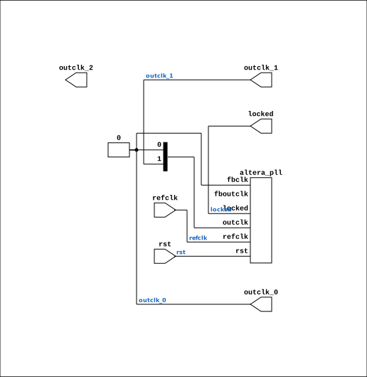
Contains: altera_pll (vendor)
Module hierarchy - All modules
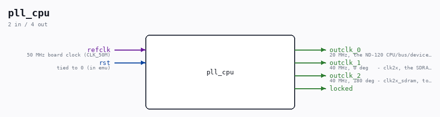
Schematic
Drawn from the Verilog: the yosys netlist of the MiSTer build, instance PLL_CPU. Sub-modules are boxes (click the picture to open it full size; there every sub-module box links to its page, and every wire shows its Verilog name).
Ports
| Direction | Width | Name | Description |
|---|---|---|---|
| input | 1 |
refclk |
50 MHz board clock (CLK_50M) |
| input | 1 |
rst |
tied to 0 (in emu) |
| output | 1 |
outclk_0 |
20 MHz, the ND-120 CPU/bus/device domain |
| output | 1 |
outclk_1 |
40 MHz, 0 deg - clk2x, the SDRAM controller |
| output | 1 |
outclk_2 |
40 MHz, 180 deg - clk2x_sdram, to the SDRAM chip |
| output | 1 |
locked |
Verilog source
Verilog/fpga/mister/rtl/pll_cpu.v on GitHub.
Show the Verilog of pll_cpu (85 lines)
//============================================================================
//! Dedicated CPU clock PLL - 50 MHz in, 20 MHz out.
//!
//! Full path: Verilog/fpga/mister/rtl/pll_cpu.v
//!
//! WHY THIS EXISTS (31-AUG-2026). The CPU clock used to be made in fabric:
//!
//!     reg clk_cpu_div = 1'b0;
//!     always @(posedge clk_sys) clk_cpu_div <= ~clk_cpu_div;
//!
//! That works perfectly in simulation and is WRONG on silicon. Quartus put
//! `emu:emu|clk_cpu_div` in the fitter's "Non-Global High Fan-Out Signals"
//! report - i.e. the clock for the ENTIRE CPU was distributed on ordinary
//! routing rather than a global clock network, so its edge arrived at
//! thousands of registers at wildly different times. The board's console,
//! panel and uptime all kept working because they run on the 40 MHz PLL
//! output, which IS global (CLKCTRL_G7); only the CPU misbehaved. That is
//! exactly the "boots in the simulator, does nothing on the board" symptom
//! this port spent a day chasing.
//!
//! TimeQuest did not catch it: it analysed the routing it was handed, met
//! the 50 ns period and reported Fmax 28.9 MHz. Meeting timing on a badly
//! distributed clock is not the same as the clock being sound.
//!
//! A PLL OUTPUT is placed on a global clock network by construction, which
//! is what every other board does - the Nexys takes clk_cpu from an MMCM
//! output, the Tang from an rPLL output. Neither divides in fabric.
//!
//! Instantiated straight from altera_pll with explicit parameters rather
//! than generated through the Quartus GUI (the same approach used for the
//! altsyncram RAMs here) - only the frequency strings differ from
//! rtl/pll/pll_0002.v, which altera_pll turns into counter settings at
//! synthesis.
//============================================================================

`timescale 1ns/10ps

module pll_cpu (
    input  wire refclk,   //! 50 MHz board clock (CLK_50M)
    input  wire rst,      //! tied to 0 (in emu)
    output wire outclk_0, //! 20 MHz, the ND-120 CPU/bus/device domain
    //! SDRAM main memory (01-SEP-2026): the sheet-49 bridge MEM_RAM_49_SDRAM
    //! runs on a 2x clock that must be EDGE-ALIGNED with the CPU clock - it
    //! samples the OSC-domain RAS/CAS/AA as synchronous signals, which is only
    //! true when both come from the SAME PLL (the Tang does exactly this with
    //! its rPLL clkout / clkoutd). So the 40 MHz pair lives here, not on the
    //! video PLL, which nd120.sdc declares asynchronous to this one.
    output wire outclk_1, //! 40 MHz, 0 deg   - clk2x, the SDRAM controller
    output wire outclk_2, //! 40 MHz, 180 deg - clk2x_sdram, to the SDRAM chip
    output wire locked
);

  altera_pll #(
      .fractional_vco_multiplier("false"),
      .reference_clock_frequency("50.0 MHz"),
      .operation_mode("direct"),
      .number_of_clocks(3),
      //! 20 MHz. MUST match nd120.qsf's BOARD_CLK_FREQ=20000000 and
      //! ND120_UART_DELAY_FRAMES=173 (20e6/115200), or the console garbles.
      // SLOW-CLOCK EXPERIMENT (01-SEP-2026, Ronny): 5 MHz instead of 20, to
      // rule out FPGA timing as the cause of the boot failure. Timing already
      // reports met with +13 ns slack at 20 MHz, but a 4x slower clock makes
      // that argument unnecessary - if the fault is identical at 5 MHz it is
      // NOT timing. nd120.qsf BOARD_CLK_FREQ must match or the console garbles.
      .output_clock_frequency0("20.000000 MHz"),
      .phase_shift0("0 ps"),
      .duty_cycle0(50),
      .output_clock_frequency1("40.000000 MHz"),
      .phase_shift1("0 ps"),
      .duty_cycle1(50),
      .output_clock_frequency2("40.000000 MHz"),
      .phase_shift2("12500 ps"),    // 180 degrees of 25 ns
      .duty_cycle2(50),
      .pll_type("General"),
      .pll_subtype("General")
  ) altera_pll_i (
      .rst      (rst),
      .outclk   ({outclk_2, outclk_1, outclk_0}),
      .locked   (locked),
      .fboutclk ( ),
      .fbclk    (1'b0),
      .refclk   (refclk)
  );

endmodule