nd120_diag_print
Source: Verilog/fpga/mister/rtl/nd120_diag_print.v
Hierarchy: not instantiated by any of the 9 build tops (elaborated by yosys).
Module hierarchy - All modules
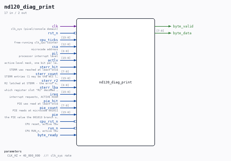
Schematic
Schematic not generated: netlistsvg failed: RangeError: Maximum call stack size exceeded.
Description
nd120_diag_print.v - CPU state, printed onto the console WHY THIS EXISTS (31-AUG-2026)
On MiSTer the console, the operator panel and the uptime counter all work - they live in the pixel clock domain - while the CPU shows no sign of life: no OPCOM '#', no echo, MIPS 00.00. Everything the build reports is clean (0 errors, WCS microcode initialised from MIF, CPU clock a real PLL output on a global network, timing met), so the remaining question is not "does a report look wrong" but "what is the CPU actually DOING". A screenshot of the running core can be pulled off the board over ssh ("screenshot" > /dev/MiSTer_cmd), so anything printed on the console can be read back without anyone watching the monitor. WHAT EACH FIELD ANSWERS
CK free-running counter clocked by clk_cpu. Proves the CPU clock is toggling in silicon and that the CPU reset was released - neither of which simulation or the timing report can tell us. CSA the microcode address. NOTE its limits: sampled once a second, it ALIASES against a tight loop and shows arbitrary points inside it, not the loop. Use nd120_csa_trace.v for the real sequence. PIL processor interrupt level. AL active-level mask. R cpu_rst_n. N RUN_n (active low). ST the self-test failure branch: hit flag / entry count, and R2 - the error number STERR exists to display (see rtl/nd120_sterr_catch.v). LB is the register slot "R2" decoded to. IQ the raw interrupt-request vector, ALREADY INVERTED by the caller so a 1 bit means "this level is requesting". The core drives it active low as DEBUG_IREQ_15_0_N; printing it raw would mean reading a wall of ones and mentally inverting every bit. Values are OCTAL. This is an octal machine and these are compared against octal microcode listings; hex would mean converting by hand every time. CLOCK DOMAINS. Everything from the CPU belongs to clk_cpu; this module runs on clk_sys and samples through two flops. That is enough for a DISPLAY - a sample taken mid-change can show a torn value for one line - but it is not a synchroniser for control logic, and this module drives nothing but text. DIAGNOSTIC SCAFFOLDING, compiled in only when ND120_DIAG_PRINT is defined. It is not part of the machine.
Parameters
| Parameter | Default |
|---|---|
CLK_HZ |
40_000_000 //! clk_sys rate |
Ports
| Direction | Width | Name | Description |
|---|---|---|---|
| input | 1 |
clk |
clk_sys (pixel/console domain) |
| input | 1 |
rst_n (active low) |
|
| input | [15:0] |
cpu_ticks |
free-running clk_cpu counter |
| input | [12:0] |
csa |
microcode address |
| input | [3:0] |
pil |
processor interrupt level |
| input | [15:0] |
actlv |
active-level mask, one bit per level |
| input | 1 |
sterr_hit |
STERR was reached at least once |
| input | [7:0] |
sterr_count |
STERR entries (1 may be the WCS loader) |
| input | [15:0] |
sterr_r2 |
R2 latched at STERR - the error number |
| input | [3:0] |
sterr_lba |
which register slot "R2" decoded to |
| input | [15:0] |
ireq |
interrupt requests, ACTIVE HIGH |
| input | 1 |
pie_hit |
PIE was read at least once |
| input | [7:0] |
pie_count |
PIE reads at microcode 001011 |
| input | [15:0] |
pie |
the PIE value the 001013 branch uses |
| input | 1 |
cpu_rst_n (active low) |
CPU reset, active low |
| input | 1 |
run_n (active low) |
CPU RUN_n, active low |
| output | 1 |
byte_valid |
|
| output | [7:0] |
byte_data |
|
| input | 1 |
byte_ready |
Verilog source
Verilog/fpga/mister/rtl/nd120_diag_print.v on GitHub.
Show the Verilog of nd120_diag_print (338 lines)
/*****************************************************************************
 *  nd120_diag_print.v - CPU state, printed onto the console                  *
 *                                                                            *
 *  WHY THIS EXISTS (31-AUG-2026)                                             *
 *  ------------------------------                                            *
 *  On MiSTer the console, the operator panel and the uptime counter all work *
 *  - they live in the pixel clock domain - while the CPU shows no sign of    *
 *  life: no OPCOM '#', no echo, MIPS 00.00. Everything the build reports is  *
 *  clean (0 errors, WCS microcode initialised from MIF, CPU clock a real PLL *
 *  output on a global network, timing met), so the remaining question is not *
 *  "does a report look wrong" but "what is the CPU actually DOING".          *
 *                                                                            *
 *  A screenshot of the running core can be pulled off the board over ssh     *
 *  ("screenshot" > /dev/MiSTer_cmd), so anything printed on the console can  *
 *  be read back without anyone watching the monitor.                         *
 *                                                                            *
 *  WHAT EACH FIELD ANSWERS                                                   *
 *  -----------------------                                                   *
 *    CK   free-running counter clocked by clk_cpu. Proves the CPU clock is   *
 *         toggling in silicon and that the CPU reset was released - neither  *
 *         of which simulation or the timing report can tell us.              *
 *    CSA  the microcode address. NOTE its limits: sampled once a second, it  *
 *         ALIASES against a tight loop and shows arbitrary points inside it, *
 *         not the loop. Use nd120_csa_trace.v for the real sequence.         *
 *    PIL  processor interrupt level.    AL  active-level mask.               *
 *    R    cpu_rst_n.                    N   RUN_n (active low).              *
 *    ST   the self-test failure branch: hit flag / entry count, and R2 -     *
 *         the error number STERR exists to display (see                      *
 *         rtl/nd120_sterr_catch.v). LB is the register slot "R2" decoded to. *
 *    IQ   the raw interrupt-request vector, ALREADY INVERTED by the caller   *
 *         so a 1 bit means "this level is requesting". The core drives it    *
 *         active low as DEBUG_IREQ_15_0_N; printing it raw would mean        *
 *         reading a wall of ones and mentally inverting every bit.           *
 *                                                                            *
 *  Values are OCTAL. This is an octal machine and these are compared against *
 *  octal microcode listings; hex would mean converting by hand every time.   *
 *                                                                            *
 *  CLOCK DOMAINS. Everything from the CPU belongs to clk_cpu; this module    *
 *  runs on clk_sys and samples through two flops. That is enough for a       *
 *  DISPLAY - a sample taken mid-change can show a torn value for one line -  *
 *  but it is not a synchroniser for control logic, and this module drives    *
 *  nothing but text.                                                         *
 *                                                                            *
 *  DIAGNOSTIC SCAFFOLDING, compiled in only when ND120_DIAG_PRINT is         *
 *  defined. It is not part of the machine.                                   *
 *****************************************************************************/

`default_nettype none

module nd120_diag_print #(
    parameter integer CLK_HZ = 40_000_000  //! clk_sys rate, sets the one-second tick
) (
    input  wire        clk,      //! clk_sys (pixel/console domain)
    input  wire        rst_n,

    // Signals from the CPU domain - sampled, see the CLOCK DOMAINS note above.
    input  wire [15:0] cpu_ticks,    //! free-running clk_cpu counter
    input  wire [12:0] csa,          //! microcode address
    input  wire [ 3:0] pil,          //! processor interrupt level
    input  wire [15:0] actlv,        //! active-level mask, one bit per level
    input  wire        sterr_hit,    //! STERR was reached at least once
    input  wire [ 7:0] sterr_count,  //! STERR entries (1 may be the WCS loader)
    input  wire [15:0] sterr_r2,     //! R2 latched at STERR - the error number
    input  wire [ 3:0] sterr_lba,    //! which register slot "R2" decoded to
    input  wire [15:0] ireq,         //! interrupt requests, ACTIVE HIGH
    input  wire        pie_hit,      //! PIE was read at least once
    input  wire [ 7:0] pie_count,    //! PIE reads at microcode 001011
    input  wire [15:0] pie,          //! the PIE value the 001013 branch uses
    input  wire        cpu_rst_n,    //! CPU reset, active low
    input  wire        run_n,        //! CPU RUN_n, active low

    // Byte stream into the console, same handshake as the CPU's own output.
    output reg         byte_valid,
    output reg  [7:0]  byte_data,
    input  wire        byte_ready
);

  //--------------------------------------------------------------------------
  // Sample the CPU-domain signals
  //--------------------------------------------------------------------------
  reg [15:0] s_ticks_m, s_ticks;
  reg [12:0] s_csa_m,   s_csa;
  reg [ 3:0] s_pil_m,   s_pil;
  reg [15:0] s_actlv_m, s_actlv;
  reg        s_shit_m,  s_shit;
  reg [ 7:0] s_scnt_m,  s_scnt;
  reg [15:0] s_sr2_m,   s_sr2;
  reg [ 3:0] s_slba_m,  s_slba;
  reg [15:0] s_ireq_m,  s_ireq;
  reg        s_phit_m,  s_phit;
  reg [ 7:0] s_pcnt_m,  s_pcnt;
  reg [15:0] s_pie_m,   s_pie;
  reg        s_rst_m,   s_rst;
  reg        s_run_m,   s_run;

  always @(posedge clk) begin
    s_ticks_m <= cpu_ticks;   s_ticks <= s_ticks_m;
    s_csa_m   <= csa;         s_csa   <= s_csa_m;
    s_pil_m   <= pil;         s_pil   <= s_pil_m;
    s_actlv_m <= actlv;       s_actlv <= s_actlv_m;
    s_shit_m  <= sterr_hit;   s_shit  <= s_shit_m;
    s_scnt_m  <= sterr_count; s_scnt  <= s_scnt_m;
    s_sr2_m   <= sterr_r2;    s_sr2   <= s_sr2_m;
    s_slba_m  <= sterr_lba;   s_slba  <= s_slba_m;
    s_ireq_m  <= ireq;        s_ireq  <= s_ireq_m;
    s_phit_m  <= pie_hit;     s_phit  <= s_phit_m;
    s_pcnt_m  <= pie_count;   s_pcnt  <= s_pcnt_m;
    s_pie_m   <= pie;         s_pie   <= s_pie_m;
    s_rst_m   <= cpu_rst_n;   s_rst   <= s_rst_m;
    s_run_m   <= run_n;       s_run   <= s_run_m;
  end

  //--------------------------------------------------------------------------
  // One-second tick
  //--------------------------------------------------------------------------
  localparam integer TICK_MAX = CLK_HZ - 1;

  reg [25:0] r_tick_cnt;
  reg        r_start;

  always @(posedge clk) begin
    if (!rst_n) begin
      r_tick_cnt <= 26'd0;
      r_start    <= 1'b0;
    end else if (r_tick_cnt >= TICK_MAX[25:0]) begin
      r_tick_cnt <= 26'd0;
      r_start    <= 1'b1;
    end else begin
      r_tick_cnt <= r_tick_cnt + 26'd1;
      r_start    <= 1'b0;
    end
  end

  //--------------------------------------------------------------------------
  // Two lines, emitted one character per accepted handshake:
  //
  //   CK nnnnnn CSA nnnnn PIL nn AL nnnnnn R n N n<CR><LF>
  //   ST n/nnn R2 nnnnnn LB nn IQ nnnnnn<CR><LF>
  //
  // Every field is latched at the START of the pair, so both lines describe
  // the same instant - fields sampled as they print would be smeared across
  // the ~80 character times the pair takes to send.
  //--------------------------------------------------------------------------
  localparam integer LEN = 98;

  reg [15:0] l_ticks;
  reg [12:0] l_csa;
  reg [ 3:0] l_pil;
  reg [15:0] l_actlv;
  reg        l_shit;
  reg [ 7:0] l_scnt;
  reg [15:0] l_sr2;
  reg [ 3:0] l_slba;
  reg [15:0] l_ireq;
  reg        l_phit;
  reg [ 7:0] l_pcnt;
  reg [15:0] l_pie;
  reg        l_rst;
  reg        l_run;

  reg [6:0]  r_idx;      //! 0..LEN-1 while sending, LEN = idle
  reg [7:0]  s_char;

  //! One octal digit, as ASCII.
  function [7:0] oct;
    input [2:0] v;
    begin
      oct = 8'h30 + {5'b0, v};
    end
  endfunction

  always @(*) begin
    case (r_idx)
      // ---- line 1 ----
      7'd0:  s_char = "C";
      7'd1:  s_char = "K";
      7'd2:  s_char = " ";
      // 16-bit counter, 6 octal digits (top digit is 1 bit wide)
      7'd3:  s_char = oct({2'b0, l_ticks[15]});
      7'd4:  s_char = oct(l_ticks[14:12]);
      7'd5:  s_char = oct(l_ticks[11:9]);
      7'd6:  s_char = oct(l_ticks[8:6]);
      7'd7:  s_char = oct(l_ticks[5:3]);
      7'd8:  s_char = oct(l_ticks[2:0]);
      7'd9:  s_char = " ";
      7'd10: s_char = "C";
      7'd11: s_char = "S";
      7'd12: s_char = "A";
      7'd13: s_char = " ";
      // 13-bit microcode address, 5 octal digits
      7'd14: s_char = oct({2'b0, l_csa[12]});
      7'd15: s_char = oct(l_csa[11:9]);
      7'd16: s_char = oct(l_csa[8:6]);
      7'd17: s_char = oct(l_csa[5:3]);
      7'd18: s_char = oct(l_csa[2:0]);
      7'd19: s_char = " ";
      7'd20: s_char = "P";
      7'd21: s_char = "I";
      7'd22: s_char = "L";
      7'd23: s_char = " ";
      7'd24: s_char = oct({2'b0, l_pil[3]});
      7'd25: s_char = oct(l_pil[2:0]);
      7'd26: s_char = " ";
      7'd27: s_char = "A";
      7'd28: s_char = "L";
      7'd29: s_char = " ";
      7'd30: s_char = oct({2'b0, l_actlv[15]});
      7'd31: s_char = oct(l_actlv[14:12]);
      7'd32: s_char = oct(l_actlv[11:9]);
      7'd33: s_char = oct(l_actlv[8:6]);
      7'd34: s_char = oct(l_actlv[5:3]);
      7'd35: s_char = oct(l_actlv[2:0]);
      7'd36: s_char = " ";
      7'd37: s_char = "R";
      7'd38: s_char = " ";
      7'd39: s_char = l_rst ? "1" : "0";
      7'd40: s_char = " ";
      7'd41: s_char = "N";
      7'd42: s_char = " ";
      7'd43: s_char = l_run ? "1" : "0";
      7'd44: s_char = 8'h0D;
      7'd45: s_char = 8'h0A;
      // ---- line 2 ----
      7'd46: s_char = "S";
      7'd47: s_char = "T";
      7'd48: s_char = " ";
      7'd49: s_char = l_shit ? "1" : "0";
      7'd50: s_char = "/";
      // 8-bit entry count, 3 octal digits (top digit is 2 bits wide)
      7'd51: s_char = oct({1'b0, l_scnt[7:6]});
      7'd52: s_char = oct(l_scnt[5:3]);
      7'd53: s_char = oct(l_scnt[2:0]);
      7'd54: s_char = " ";
      7'd55: s_char = "R";
      7'd56: s_char = "2";
      7'd57: s_char = " ";
      7'd58: s_char = oct({2'b0, l_sr2[15]});
      7'd59: s_char = oct(l_sr2[14:12]);
      7'd60: s_char = oct(l_sr2[11:9]);
      7'd61: s_char = oct(l_sr2[8:6]);
      7'd62: s_char = oct(l_sr2[5:3]);
      7'd63: s_char = oct(l_sr2[2:0]);
      7'd64: s_char = " ";
      7'd65: s_char = "L";
      7'd66: s_char = "B";
      7'd67: s_char = " ";
      7'd68: s_char = oct({2'b0, l_slba[3]});
      7'd69: s_char = oct(l_slba[2:0]);
      7'd70: s_char = " ";
      7'd71: s_char = "I";
      7'd72: s_char = "Q";
      7'd73: s_char = " ";
      7'd74: s_char = oct({2'b0, l_ireq[15]});
      7'd75: s_char = oct(l_ireq[14:12]);
      7'd76: s_char = oct(l_ireq[11:9]);
      7'd77: s_char = oct(l_ireq[8:6]);
      7'd78: s_char = oct(l_ireq[5:3]);
      7'd79: s_char = oct(l_ireq[2:0]);
      // PIE, latched at microcode 001011 - the value the 001013 branch is
      // decided on, and the first place this board diverges from a booting
      // machine. n/nnn is hit/count, the same shape as ST above.
      7'd80: s_char = " ";
      7'd81: s_char = "P";
      7'd82: s_char = "E";
      7'd83: s_char = " ";
      7'd84: s_char = l_phit ? "1" : "0";
      7'd85: s_char = "/";
      7'd86: s_char = oct({1'b0, l_pcnt[7:6]});
      7'd87: s_char = oct(l_pcnt[5:3]);
      7'd88: s_char = oct(l_pcnt[2:0]);
      7'd89: s_char = " ";
      7'd90: s_char = oct({2'b0, l_pie[15]});
      7'd91: s_char = oct(l_pie[14:12]);
      7'd92: s_char = oct(l_pie[11:9]);
      7'd93: s_char = oct(l_pie[8:6]);
      7'd94: s_char = oct(l_pie[5:3]);
      7'd95: s_char = oct(l_pie[2:0]);
      7'd96: s_char = 8'h0D;
      7'd97: s_char = 8'h0A;
      default: s_char = " ";
    endcase
  end

  always @(posedge clk) begin
    if (!rst_n) begin
      r_idx      <= LEN[6:0];
      byte_valid <= 1'b0;
      byte_data  <= 8'h00;
      l_ticks    <= 16'd0;
      l_csa      <= 13'd0;
      l_pil      <= 4'd0;
      l_actlv    <= 16'd0;
      l_shit     <= 1'b0;
      l_scnt     <= 8'd0;
      l_sr2      <= 16'd0;
      l_slba     <= 4'd0;
      l_ireq     <= 16'd0;
      l_phit     <= 1'b0;
      l_pcnt     <= 8'd0;
      l_pie      <= 16'd0;
      l_rst      <= 1'b0;
      l_run      <= 1'b0;
    end else begin
      if (r_idx == LEN[6:0]) begin
        // Idle. A tick starts the pair and freezes the values it will show.
        byte_valid <= 1'b0;
        if (r_start) begin
          l_ticks <= s_ticks;
          l_csa   <= s_csa;
          l_pil   <= s_pil;
          l_actlv <= s_actlv;
          l_shit  <= s_shit;
          l_scnt  <= s_scnt;
          l_sr2   <= s_sr2;
          l_slba  <= s_slba;
          l_ireq  <= s_ireq;
          l_phit  <= s_phit;
          l_pcnt  <= s_pcnt;
          l_pie   <= s_pie;
          l_rst   <= s_rst;
          l_run   <= s_run;
          r_idx   <= 7'd0;
        end
      end else begin
        // Sending. Hold the character until the console takes it.
        byte_valid <= 1'b1;
        byte_data  <= s_char;
        if (byte_valid && byte_ready) begin
          byte_valid <= 1'b0;
          r_idx      <= r_idx + 7'd1;
        end
      end
    end
  end

endmodule

`default_nettype wire