nd120_csa_trace
Source: Verilog/fpga/mister/rtl/nd120_csa_trace.v
Hierarchy: not instantiated by any of the 9 build tops (elaborated by yosys).
Module hierarchy - All modules
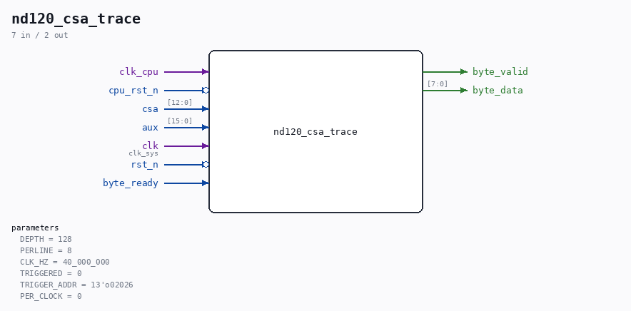
Schematic
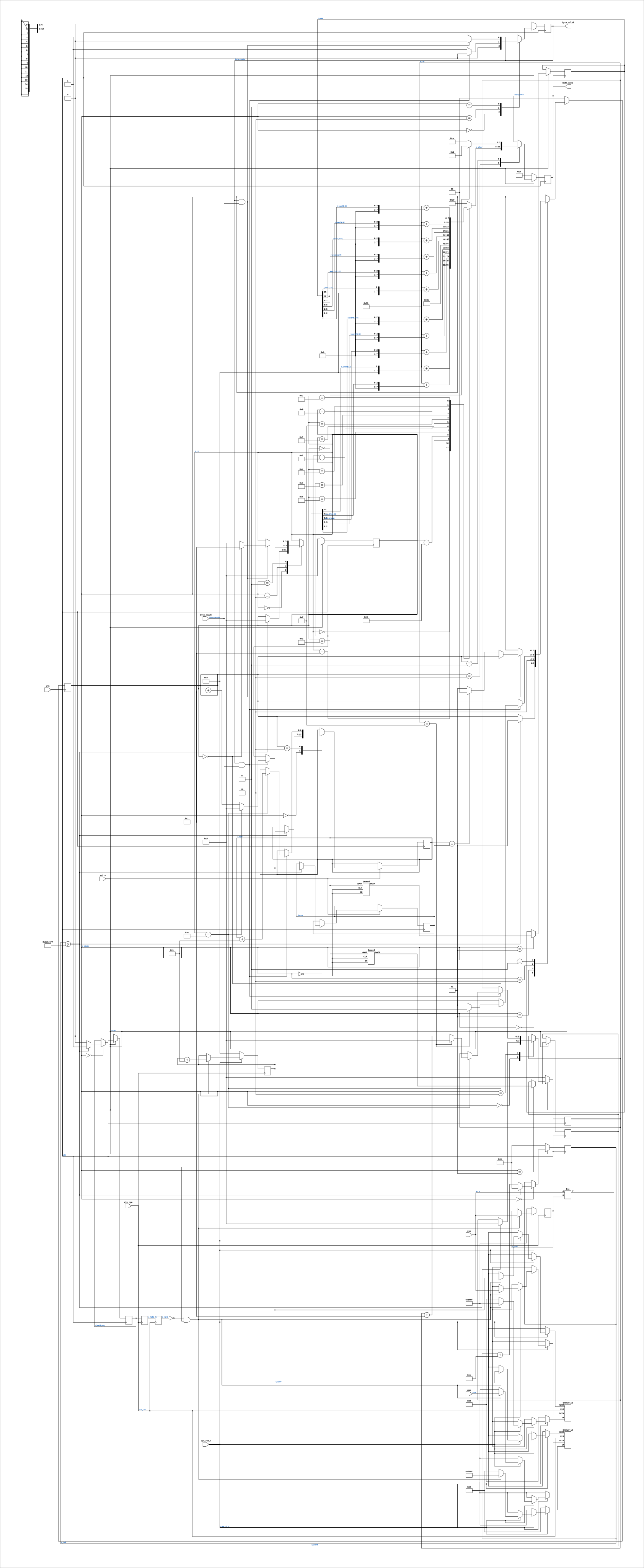
Drawn from the Verilog: no build top uses this module, so it was elaborated from its own file with no defines and default parameters. Sub-modules are boxes (click the picture to open it full size; there every sub-module box links to its page, and every wire shows its Verilog name).
Description
nd120_csa_trace.v - print the last N microcode addresses, in order WHY (01-SEP-2026)
nd120_diag_print.v samples CSA once a second and showed the MiSTer board visiting about eleven microcode addresses over and over. That was misleading: one sample per second against a tight loop ALIASES, so the eleven addresses were arbitrary points inside the loop, not the loop itself. The giveaway was that two different builds printed the same eleven values in the same order - a sampler hitting a periodic signal. To identify what the microcode is actually doing, the CONSECUTIVE sequence is needed, which is exactly what Verilator's csa_trace.csv gives for a machine that boots. This module produces the same thing from silicon: a circular buffer of the last DEPTH microcode addresses, dumped to the console as octal so it can be read off a screenshot and diffed against the simulator's trace. Only CHANGES are recorded, one entry per new address, matching how csa_trace.csv is written - otherwise a slow microinstruction would fill the buffer with copies of itself. CLOCK DOMAINS. Capture runs on clk_cpu; the dump runs on clk_sys. The buffer is FROZEN while dumping (r_hold), so the reader sees a still picture rather than entries changing under it. That costs nothing here - the machine is stuck in a loop, so the next snapshot shows the same loop. DIAGNOSTIC SCAFFOLDING, built only under ND120_DIAG_PRINT. Not part of the machine.
Parameters
| Parameter | Default |
|---|---|
DEPTH |
128 |
PERLINE |
8 |
CLK_HZ |
40_000_000 |
TRIGGERED |
0 |
TRIGGER_ADDR |
13'o02026 |
PER_CLOCK |
0 |
Ports
| Direction | Width | Name | Description |
|---|---|---|---|
| input | 1 |
clk_cpu |
|
| input | 1 |
cpu_rst_n (active low) |
|
| input | [12:0] |
csa |
|
| input | [15:0] |
aux |
|
| input | 1 |
clk |
clk_sys |
| input | 1 |
rst_n (active low) |
|
| output | 1 |
byte_valid |
|
| output | [7:0] |
byte_data |
|
| input | 1 |
byte_ready |
Verilog source
Verilog/fpga/mister/rtl/nd120_csa_trace.v on GitHub.
Show the Verilog of nd120_csa_trace (277 lines)
/*****************************************************************************
 *  nd120_csa_trace.v - print the last N microcode addresses, in order        *
 *                                                                            *
 *  WHY (01-SEP-2026)                                                         *
 *  ----------------                                                          *
 *  nd120_diag_print.v samples CSA once a second and showed the MiSTer board  *
 *  visiting about eleven microcode addresses over and over. That was         *
 *  misleading: one sample per second against a tight loop ALIASES, so the    *
 *  eleven addresses were arbitrary points inside the loop, not the loop      *
 *  itself. The giveaway was that two different builds printed the same       *
 *  eleven values in the same order - a sampler hitting a periodic signal.    *
 *                                                                            *
 *  To identify what the microcode is actually doing, the CONSECUTIVE         *
 *  sequence is needed, which is exactly what Verilator's csa_trace.csv       *
 *  gives for a machine that boots. This module produces the same thing from  *
 *  silicon: a circular buffer of the last DEPTH microcode addresses, dumped  *
 *  to the console as octal so it can be read off a screenshot and diffed     *
 *  against the simulator's trace.                                            *
 *                                                                            *
 *  Only CHANGES are recorded, one entry per new address, matching how        *
 *  csa_trace.csv is written - otherwise a slow microinstruction would fill   *
 *  the buffer with copies of itself.                                         *
 *                                                                            *
 *  CLOCK DOMAINS. Capture runs on clk_cpu; the dump runs on clk_sys. The     *
 *  buffer is FROZEN while dumping (r_hold), so the reader sees a still       *
 *  picture rather than entries changing under it. That costs nothing here -  *
 *  the machine is stuck in a loop, so the next snapshot shows the same loop. *
 *                                                                            *
 *  DIAGNOSTIC SCAFFOLDING, built only under ND120_DIAG_PRINT. Not part of    *
 *  the machine.                                                              *
 *****************************************************************************/

`default_nettype none

module nd120_csa_trace #(
    //! entries kept. MUST be a power of two - the buffer wraps on {AW{1'b1}},
    //! so a non-power-of-two would write past the end of the array.
    parameter integer DEPTH   = 128,
    parameter integer PERLINE = 8,    //! entries per printed line
    parameter integer CLK_HZ  = 40_000_000,  //! clk_sys, sets the repeat interval

    //! TRIGGERED CAPTURE (01-SEP-2026). 0 = free-running circular buffer: the
    //! last DEPTH transitions, which is what identified the steady-state loop.
    //! 1 = wait until CSA first equals TRIGGER_ADDR, then record the next
    //! DEPTH transitions and FREEZE.
    //!
    //! Why the triggered mode was needed: the loop is understood, but the
    //! question moved to a ONE-OFF event - MACL calls RIIE1 from 002026 with
    //! return address 002027, and on this board the return lands on 001021
    //! instead. A circular buffer only ever shows the steady state it settles
    //! into, and a from-reset capture would need to be millions of entries
    //! deep to reach the interesting moment. Arming on the address puts the
    //! window exactly where the divergence is.
    parameter integer    TRIGGERED    = 0,
    parameter [12:0]     TRIGGER_ADDR = 13'o02026,

    //! 0 = record on each ADDRESS CHANGE (one entry per microinstruction).
    //! 1 = record EVERY clk_cpu once armed.
    //!
    //! Per-clock is what shows the CYCLE WAVEFORM. Measured 01-SEP-2026: this
    //! board fires 1.89x as many bus-cycle terminates as a machine that boots,
    //! over identical microcode - so cycles are being cut short. One sample
    //! per microinstruction cannot show how many clocks a cycle lasted; only
    //! a per-clock record can, and that is what says WHICH terminate term is
    //! firing early.
    parameter integer    PER_CLOCK    = 0
) (
    input  wire        clk_cpu,
    input  wire        cpu_rst_n,
    input  wire [12:0] csa,
    //! A bus recorded ALONGSIDE each address, printed as "csa:aux". Added
    //! 01-SEP-2026 after a single-sample comparison of FIDBO against the
    //! simulator produced a false result: the board latched one
    //! microinstruction earlier than the sim printed, so a value the working
    //! machine also produces looked like a divergence. Recording the pair per
    //! entry gives the same WINDOW the sim dumps, so like is compared with
    //! like instead of point against point.
    input  wire [15:0] aux,

    input  wire        clk,     //! clk_sys
    input  wire        rst_n,

    output reg         byte_valid,
    output reg  [7:0]  byte_data,
    input  wire        byte_ready
);

  localparam integer AW = $clog2(DEPTH);

  //--------------------------------------------------------------------------
  // Capture (clk_cpu)
  //--------------------------------------------------------------------------
  reg [12:0] mem     [0:DEPTH-1];
  reg [15:0] mem_aux [0:DEPTH-1];
  reg [AW-1:0] r_wptr = {AW{1'b0}};
  reg [12:0]   r_prev = 13'h1FFF;

  // Freeze request, crossed into the CPU domain.
  reg        r_hold_req;             // set by the dumper (clk_sys)
  reg        r_hold_m, r_hold;       // synchronised into clk_cpu

  reg r_armed = 1'b0;   //! triggered mode: the trigger address has been seen
  reg r_full  = 1'b0;   //! triggered mode: DEPTH entries recorded, stop

  always @(posedge clk_cpu) begin
    r_hold_m <= r_hold_req;
    r_hold   <= r_hold_m;

    if (!cpu_rst_n) begin
      r_wptr <= {AW{1'b0}};
      r_prev <= 13'h1FFF;
      r_armed <= 1'b0;
      r_full  <= 1'b0;
    end else if (TRIGGERED != 0) begin
      // Arm on the first sight of the trigger address, then record the next
      // DEPTH transitions and stop. Freezing matters: the point of this mode
      // is a ONE-OFF event, so the buffer must not be overwritten by the loop
      // the machine settles into afterwards.
      if (!r_armed) begin
        if (csa == TRIGGER_ADDR) begin
          r_armed     <= 1'b1;
          mem[r_wptr]     <= csa;   // keep the trigger itself as entry 0
          mem_aux[r_wptr] <= aux;
          r_wptr      <= r_wptr + {{(AW-1){1'b0}}, 1'b1};
          r_prev      <= csa;
        end
      end else if (!r_full && (PER_CLOCK != 0 || csa != r_prev)) begin
        // PER_CLOCK: record every clock, so a cycle that lasts N clocks
        // occupies N entries and its length is readable straight off the dump.
        mem[r_wptr]     <= csa;
        mem_aux[r_wptr] <= aux;
        r_wptr          <= r_wptr + {{(AW-1){1'b0}}, 1'b1};
        r_prev          <= csa;
        if (r_wptr == {AW{1'b1}}) r_full <= 1'b1;   // last slot just written
      end
    end else if (!r_hold && csa != r_prev) begin
      mem[r_wptr]     <= csa;
      mem_aux[r_wptr] <= aux;
      r_wptr          <= r_wptr + {{(AW-1){1'b0}}, 1'b1};
      r_prev          <= csa;
    end
  end

  //--------------------------------------------------------------------------
  // Dump (clk_sys)
  //
  // Oldest first: start reading at the write pointer, which is where the
  // next entry would go and therefore the oldest one still held.
  //--------------------------------------------------------------------------
  localparam integer TICK_MAX = (CLK_HZ * 5) - 1;   // one dump every 5 seconds

  reg [27:0] r_tick;
  reg [AW-1:0] r_rptr;
  reg [AW-1:0] r_base;
  reg [12:0]   r_word;
  reg [15:0]   r_aux;
  reg [3:0]    r_col;     // 0..PERLINE-1, entries printed on this line
  //! character within one entry: "ccccc:aaaaaa " = 5 + 1 + 6 + 1 = 13
  reg [3:0]    r_ch;
  reg [1:0]    r_state;
  localparam [3:0] CH_LAST = 4'd12;

  localparam ST_IDLE = 2'd0,
             ST_LOAD = 2'd1,
             ST_EMIT = 2'd2,
             ST_EOL  = 2'd3;

  function [7:0] oct;
    input [2:0] v;
    begin
      oct = 8'h30 + {5'b0, v};
    end
  endfunction

  reg [7:0] s_char;
  always @(*) begin
    case (r_ch)
      // the microcode address, 5 octal digits
      4'd0:  s_char = oct({2'b0, r_word[12]});
      4'd1:  s_char = oct(r_word[11:9]);
      4'd2:  s_char = oct(r_word[8:6]);
      4'd3:  s_char = oct(r_word[5:3]);
      4'd4:  s_char = oct(r_word[2:0]);
      4'd5:  s_char = ":";
      // the bus sampled with it, 6 octal digits
      4'd6:  s_char = oct({2'b0, r_aux[15]});
      4'd7:  s_char = oct(r_aux[14:12]);
      4'd8:  s_char = oct(r_aux[11:9]);
      4'd9:  s_char = oct(r_aux[8:6]);
      4'd10: s_char = oct(r_aux[5:3]);
      4'd11: s_char = oct(r_aux[2:0]);
      default: s_char = " ";
    endcase
  end

  always @(posedge clk) begin
    if (!rst_n) begin
      r_state    <= ST_IDLE;
      r_tick     <= 28'd0;
      r_hold_req <= 1'b0;
      byte_valid <= 1'b0;
      byte_data  <= 8'h00;
      r_col      <= 4'd0;
      r_ch       <= 4'd0;
    end else begin
      case (r_state)
        ST_IDLE: begin
          byte_valid <= 1'b0;
          r_hold_req <= 1'b0;
          if (r_tick >= TICK_MAX[27:0]) begin
            r_tick     <= 28'd0;
            r_hold_req <= 1'b1;
            // Circular mode: the oldest entry is where the next write would
            // go, so start at the write pointer. Triggered mode: the buffer
            // was filled once from index 0, so start there and read forward.
            r_base     <= (TRIGGERED != 0) ? {AW{1'b0}} : r_wptr;
            r_rptr     <= (TRIGGERED != 0) ? {AW{1'b0}} : r_wptr;
            r_col      <= 4'd0;
            r_ch       <= 4'd0;
            r_state    <= ST_LOAD;
          end else begin
            r_tick <= r_tick + 28'd1;
          end
        end

        ST_LOAD: begin
          r_word <= mem[r_rptr];
          r_aux  <= mem_aux[r_rptr];
          r_state <= ST_EMIT;
        end

        ST_EMIT: begin
          byte_valid <= 1'b1;
          byte_data  <= s_char;
          if (byte_valid && byte_ready) begin
            byte_valid <= 1'b0;
            if (r_ch == CH_LAST) begin
              r_ch  <= 4'd0;
              r_rptr <= r_rptr + {{(AW-1){1'b0}}, 1'b1};
              if (r_col == PERLINE[3:0] - 4'd1) begin
                r_col   <= 4'd0;
                r_ch    <= 4'd0;
                r_state <= ST_EOL;
              end else begin
                r_col   <= r_col + 4'd1;
                r_state <= ST_LOAD;
              end
            end else begin
              r_ch <= r_ch + 4'd1;
            end
          end
        end

        ST_EOL: begin
          byte_valid <= 1'b1;
          byte_data  <= (r_ch == 4'd0) ? 8'h0D : 8'h0A;
          if (byte_valid && byte_ready) begin
            byte_valid <= 1'b0;
            if (r_ch == 4'd0) begin
              r_ch <= 4'd1;
            end else begin
              r_ch <= 4'd0;
              // Wrapped back to where the dump began: the whole buffer is out.
              if (r_rptr == r_base) r_state <= ST_IDLE;
              else                  r_state <= ST_LOAD;
            end
          end
        end

        default: r_state <= ST_IDLE;
      endcase
    end
  end

endmodule

`default_nettype wire