key_vt100
Source: Verilog/Terminals/rtl/key_vt100.v
Hierarchy: not instantiated by any of the 9 build tops (elaborated by yosys).
Module hierarchy - All modules
Schematic
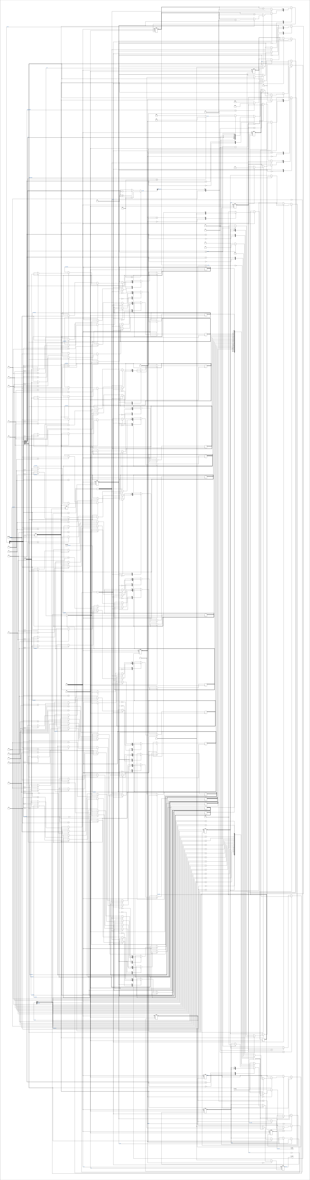
Drawn from the Verilog: no build top uses this module, so it was elaborated from its own file with no defines and default parameters. Sub-modules are boxes (click the picture to open it full size; there every sub-module box links to its page, and every wire shows its Verilog name).
Ports
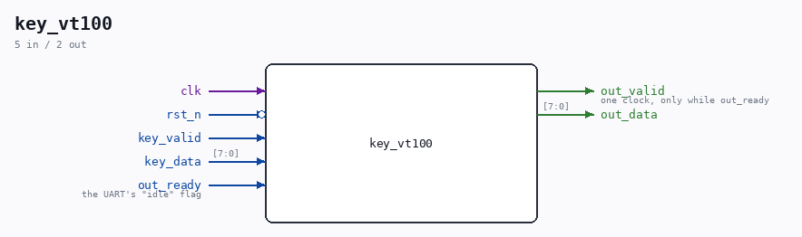
| Direction | Width | Name | Description |
|---|---|---|---|
| input | 1 |
clk |
|
| input | 1 |
rst_n (active low) |
|
| input | 1 |
key_valid |
|
| input | [7:0] |
key_data |
|
| output | 1 |
out_valid |
one clock, only while out_ready |
| output | [7:0] |
out_data |
|
| input | 1 |
out_ready |
the UART's "idle" flag |
Verilog source
Verilog/Terminals/rtl/key_vt100.v on GitHub.
Show the Verilog of key_vt100 (205 lines)
//============================================================================
//! VT100 key-sequence expander - markers in, wire bytes out
//!
//! Part of the board-independent terminal core (Verilog/Terminals/).
//!
//! Sits between the keyboard decoder and the console UART TX. Ordinary bytes
//! pass through unchanged; a SEQUENCE MARKER (bit 7 set, written by
//! ps2_ascii_table.v) becomes a whole DEC escape sequence. The marker's
//! bits 6:5 select the family, bits 4:0 the payload
//! (docs/SPEC-vt100-keys.md):
//!
//!   100f_ffff  ->  ESC [ <0x40+f>   arrows (f 1..4 = A B C D)
//!   101f_ffff  ->  ESC O <0x40+f>   DEC PF1-PF4 (f 16..19 = P Q R S)
//!   110n_nnnn  ->  ESC [ <n> ~      editing keys n=1..6, F5-F12 n=15..24
//!                                   (n printed as one or two ASCII digits)
//!   111x_xxxx  ->  nothing          reserved, dropped
//!
//! This is what makes the keyboard speak VT100 (SINTRAN terminal type 6):
//! one keypress, three to five bytes on the wire.
//!
//! WHY THE FIFO. The UART needs ~870 us for a byte at 115200-7E1 and this
//! expander hands it up to five at once - without buffering, most of them
//! would be lost (which is why the single-byte TDV encoding never needed
//! this module). Sixteen entries is three worst-case sequences of headroom;
//! keypresses are milliseconds apart, so the FIFO in practice never holds
//! more than one sequence.
//!
//! HANDSHAKE, downstream side: console_uart_tx's contract is "byte_valid one
//! clock; ignored unless ready", with ready = idle. So this module pulses
//! out_valid for exactly one clock while out_ready is high, then waits for
//! ready to DROP (the byte was taken) and rise again (the frame finished)
//! before offering the next byte. If ready did not drop - which the current
//! UART cannot do, but a future one might - the byte is offered again rather
//! than lost.
//!
//! Upstream side: key_valid is a one-clock strobe with no backpressure (the
//! PS/2 decoder cannot wait). A marker takes up to five clocks to push; a
//! key landing INSIDE that window would be dropped - at 40 MHz that window
//! is ~125 ns against keypresses milliseconds apart, so it cannot happen
//! from a keyboard. A full FIFO also drops (and a full FIFO from typing
//! means the machine end is stuck, where dropped keys are the least of it).
//!
//! Written 30-AUG-2026.
//============================================================================

`default_nettype none

module key_vt100 (
    input wire clk,
    input wire rst_n,

    // From the keyboard decoder - strobes, no backpressure
    input wire       key_valid,
    input wire [7:0] key_data,

    // To the console UART TX
    output reg        out_valid,  //! one clock, only while out_ready
    output reg  [7:0] out_data,
    input  wire       out_ready   //! the UART's "idle" flag
);

  localparam [7:0] ESC = 8'h1B;

  //--------------------------------------------------------------------------
  // The FIFO - 16 bytes, pointers one bit wider than the index so full and
  // empty are distinct (same construction as byte_fifo.v).
  //--------------------------------------------------------------------------
  reg [7:0] s_mem[0:15];
  reg [4:0] s_wptr, s_rptr;

  wire s_empty = (s_wptr == s_rptr);
  wire s_full  = (s_wptr[4] != s_rptr[4]) && (s_wptr[3:0] == s_rptr[3:0]);

  //--------------------------------------------------------------------------
  // Push side - expands a marker over up to five clocks. The marker cycle
  // pushes ESC and lines up the REST of the sequence in s_q0..s_q3; the
  // following cycles push those one per clock.
  //--------------------------------------------------------------------------
  localparam PU_IDLE = 1'b0;
  localparam PU_SEQ  = 1'b1;

  reg       s_push;
  reg [7:0] s_q0, s_q1, s_q2, s_q3;  //! the bytes after ESC
  reg [2:0] s_len;                   //! how many of them (2..4)
  reg [2:0] s_idx;

  //! The tilde family's parameter as one or two ASCII digits. n is 1..24 by
  //! construction of the table; a two-digit n has tens digit 1 or 2.
  wire [4:0] s_n     = key_data[4:0];
  wire       s_two   = (s_n >= 5'd10);
  wire [7:0] s_tens  = (s_n >= 5'd20) ? "2" : "1";
  wire [4:0] s_ones5 = (s_n >= 5'd20) ? (s_n - 5'd20)
                     : (s_n >= 5'd10) ? (s_n - 5'd10) : s_n;
  wire [7:0] s_ones  = {4'h3, s_ones5[3:0]};  //! ASCII digit

  //--------------------------------------------------------------------------
  // Pop side - one UART handshake at a time
  //--------------------------------------------------------------------------
  localparam [1:0] PO_IDLE = 2'd0;
  localparam [1:0] PO_TAKE = 2'd1;  //! offered; waiting to see ready drop

  reg [1:0] s_pop;
  reg       s_po_seen;  //! PO_TAKE has been through one full cycle

  always @(posedge clk or negedge rst_n) begin
    if (!rst_n) begin
      s_wptr    <= 5'd0;
      s_rptr    <= 5'd0;
      s_push    <= PU_IDLE;
      s_q0 <= 8'd0; s_q1 <= 8'd0; s_q2 <= 8'd0; s_q3 <= 8'd0;
      s_len <= 3'd0; s_idx <= 3'd0;
      s_pop     <= PO_IDLE;
      out_valid <= 1'b0;
      out_data  <= 8'd0;
    end else begin
      out_valid <= 1'b0;

      // ---- push ----
      case (s_push)
        PU_IDLE: begin
          if (key_valid && !s_full) begin
            if (!key_data[7]) begin
              s_mem[s_wptr[3:0]] <= key_data;
              s_wptr <= s_wptr + 5'd1;
            end else if (key_data[6:5] != 2'b11) begin
              // A marker: ESC now, the rest lined up for PU_SEQ.
              s_mem[s_wptr[3:0]] <= ESC;
              s_wptr <= s_wptr + 5'd1;
              s_push <= PU_SEQ;
              s_idx  <= 3'd0;
              case (key_data[6:5])
                2'b00: begin  // ESC [ <final>
                  s_q0  <= "[";
                  s_q1  <= {2'b01, 1'b0, key_data[4:0]};  // 0x40 + payload
                  s_len <= 3'd2;
                end
                2'b01: begin  // ESC O <char>
                  s_q0  <= "O";
                  s_q1  <= {2'b01, 1'b0, key_data[4:0]};
                  s_len <= 3'd2;
                end
                default: begin  // 2'b10: ESC [ <n> ~
                  s_q0 <= "[";
                  if (s_two) begin
                    s_q1  <= s_tens;
                    s_q2  <= s_ones;
                    s_q3  <= "~";
                    s_len <= 3'd4;
                  end else begin
                    s_q1  <= s_ones;
                    s_q2  <= "~";
                    s_len <= 3'd3;
                  end
                end
              endcase
            end
            // family 111x_xxxx: reserved - dropped without a byte
          end
        end
        PU_SEQ: begin
          if (!s_full) begin
            s_mem[s_wptr[3:0]] <= (s_idx == 3'd0) ? s_q0
                                : (s_idx == 3'd1) ? s_q1
                                : (s_idx == 3'd2) ? s_q2 : s_q3;
            s_wptr <= s_wptr + 5'd1;
            if (s_idx == s_len - 3'd1) s_push <= PU_IDLE;
            else s_idx <= s_idx + 3'd1;
          end
        end
        default: s_push <= PU_IDLE;
      endcase

      // ---- pop ----
      case (s_pop)
        PO_IDLE: begin
          s_po_seen <= 1'b0;
          if (!s_empty && out_ready) begin
            out_valid <= 1'b1;
            out_data  <= s_mem[s_rptr[3:0]];
            s_pop     <= PO_TAKE;
          end
        end
        PO_TAKE: begin
          // TIMING, counted in edges. The offer was committed at edge k, so
          // valid is high during cycle k+1 and the UART accepts at edge k+1;
          // its busy flag is then visible (ready low) during cycle k+2 -
          // which is the SECOND PO_TAKE cycle. So: the first cycle here can
          // never see the drop and is skipped; from the second on, ready low
          // = taken (advance), ready still high = the UART ignored the pulse,
          // and PO_IDLE re-offers the same byte rather than losing it.
          if (!s_po_seen) begin
            s_po_seen <= 1'b1;
          end else begin
            if (!out_ready) s_rptr <= s_rptr + 5'd1;
            s_pop <= PO_IDLE;
          end
        end
        default: s_pop <= PO_IDLE;
      endcase
    end
  end

endmodule

`default_nettype wire