term_panel
Source: Verilog/Terminals/rtl/term_panel.v
Where it sits (Nexys): nd120_nexys4ddr_top > terminal_top > term_panel
- instance path: TERMINAL.g_panel.PANEL
Used in: terminal_top (Nexys, MiSTer, MEGA65 R6, MEGA65 R3)
Contains: font_rom, term_panel_rom
Module hierarchy - All modules
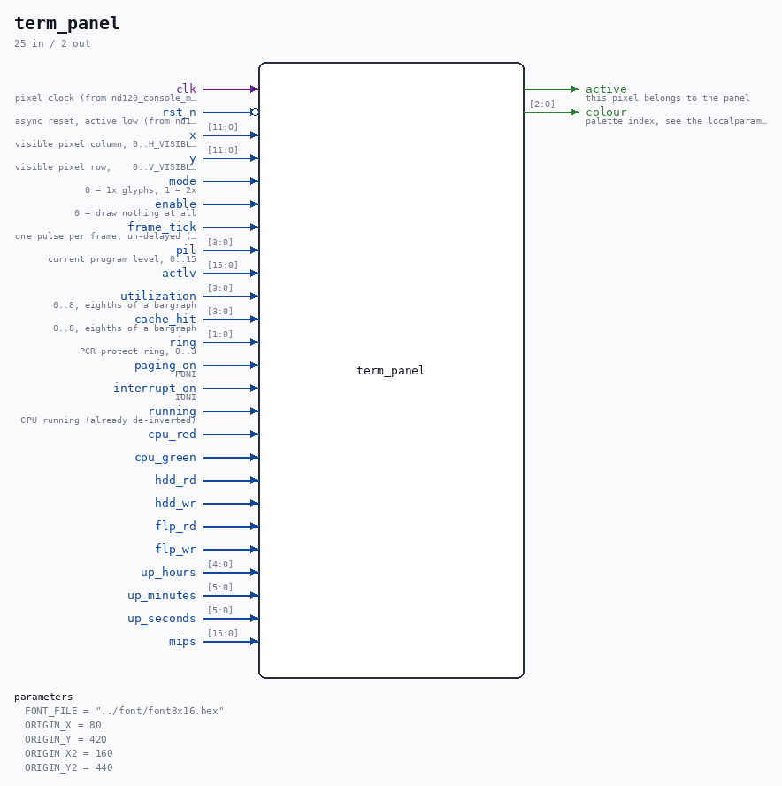
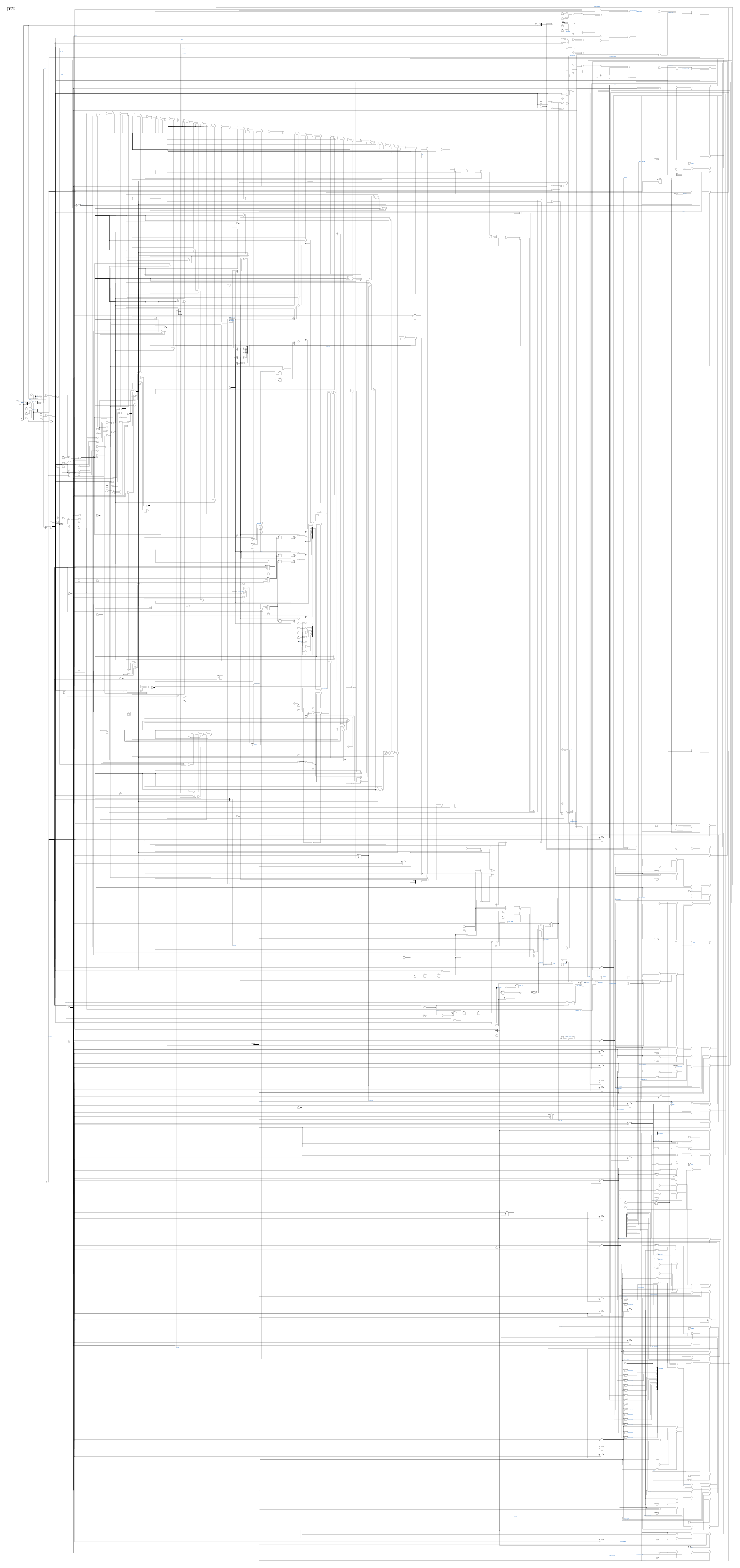
Schematic
Drawn from the Verilog: the yosys netlist of the Nexys 4 DDR build, instance TERMINAL.g_panel.PANEL. Sub-modules are boxes (click the picture to open it full size; there every sub-module box links to its page, and every wire shows its Verilog name).
Parameters
| Parameter | Default |
|---|---|
FONT_FILE |
"../font/font8x16.hex" |
ORIGIN_X |
80 |
ORIGIN_Y |
420 |
ORIGIN_X2 |
160 |
ORIGIN_Y2 |
440 |
Ports
| Direction | Width | Name | Description |
|---|---|---|---|
| input | 1 |
clk |
pixel clock (from nd120_console_mega65.clk and others) |
| input | 1 |
rst_n (active low) |
async reset, active low (from nd120_console_mega65.rst_n and others) |
| input | [11:0] |
x |
visible pixel column, 0..H_VISIBLE-1 (only valid while de) (from vga_timing.x) |
| input | [11:0] |
y |
visible pixel row, 0..V_VISIBLE-1 (only valid while de) (from vga_timing.y) |
| input | 1 |
mode |
0 = 1x glyphs, 1 = 2x |
| input | 1 |
enable |
0 = draw nothing at all |
| input | 1 |
frame_tick |
one pulse per frame, un-delayed (for blink) (from text_screen.frame_end) |
| input | [3:0] |
pil |
current program level, 0..15 |
| input | [15:0] |
actlv |
|
| input | [3:0] |
utilization |
0..8, eighths of a bargraph |
| input | [3:0] |
cache_hit |
0..8, eighths of a bargraph |
| input | [1:0] |
ring |
PCR protect ring, 0..3 |
| input | 1 |
paging_on |
PONI |
| input | 1 |
interrupt_on |
IONI |
| input | 1 |
running |
CPU running (already de-inverted) |
| input | 1 |
cpu_red |
|
| input | 1 |
cpu_green |
|
| input | 1 |
hdd_rd |
|
| input | 1 |
hdd_wr |
|
| input | 1 |
flp_rd |
|
| input | 1 |
flp_wr |
|
| input | [4:0] |
up_hours |
|
| input | [5:0] |
up_minutes |
|
| input | [5:0] |
up_seconds |
|
| input | [15:0] |
mips |
|
| output | 1 |
active |
this pixel belongs to the panel |
| output | [2:0] |
colour |
palette index, see the localparams below |
Verilog source
Verilog/Terminals/rtl/term_panel.v on GitHub.
Show the Verilog of term_panel (762 lines)
//============================================================================
//! ND-120 operator panel, drawn below the console text.
//!
//! Part of the board-independent terminal core (Verilog/Terminals/).
//!
//! Recreates the machine's own folio panel in the empty screen area under the
//! 80x25 grid. Geometry and legends come from the photographed hardware
//! (Pictures/ronny/20230618_193546.jpg, active-levels.png), and the FIELDS come
//! from the original schematic: the ND-120's panel processor - an MC68705U3 at
//! board position 35C, sheet 40 of 50 dated 5-OCT-1987, transcribed in this
//! repo as IO_PANCAL_40.v - samples exactly these signals on its Port D:
//!
//!   PD0/PD1  PCR0/PCR1   -> PROTECT RING
//!   PD2      PONI        -> PAGING     ON/OFF
//!   PD3      IONI        -> INTERRUPT  ON/OFF
//!   PD4      LHIT        -> CACHE HIT RATE
//!   PD5      LEV0        -> UTILIZATION   (idle == running at level 0)
//!
//! So the panel is a VIEW of signals the machine already computes. Nothing here
//! is invented, and where a field has no honest source it is not drawn.
//!
//! TWO DELIBERATE DEPARTURES FROM THE REAL PANEL, both because the alternative
//! would be a display that looks right and is wrong:
//!
//!   CURRENT LEVEL, not ACTIVE LEVEL. The real display lights every level that
//!   is active at once, fed from the microprogram in PANC packets, with
//!   afterglow so a single instruction on a level stays visible. We have PIL -
//!   the one level running now. The picture would be identical and the claim
//!   would not, so the caption is changed. There is NO afterglow any more: a
//!   lamp shows the levels used during the frame being drawn, and nothing
//!   older (see the per-frame occupancy note below for why the afterglow was
//!   the bug that lit the whole row).
//!
//!   UP:hh:mm:ss, not DAY/TIME. The real clock is a battery-backed MM58274 that
//!   survives a power failure. There is no panel processor in our RTL and no
//!   calendar; this counts from reset and is labelled as uptime.
//!
//! It has its OWN font ROM rather than sharing the console's. That costs about
//! two block RAMs and buys the absence of an arbiter between two renderers on a
//! 2-clock pipeline - a trade worth making on a part with 100+ of them.
//!
//! Written 28-AUG-2026.
//============================================================================

`default_nettype none

module term_panel #(
    parameter FONT_FILE = "../font/font8x16.hex",

    //! Where the panel sits, in LOGICAL pixels (before the mode's 2x scaling).
    //! 80 columns of 8 pixels is 640 wide - the same width as the console grid,
    //! which is why it lines up underneath it with no arithmetic.
    parameter integer ORIGIN_X = 80,
    parameter integer ORIGIN_Y = 420,

    //! Mode-1 origin, also in LOGICAL pixels - i.e. physical/2, because at 2x
    //! every logical pixel lasts two real ones. The text grid sits differently
    //! in the two modes, so the panel has to as well; sharing one origin is
    //! what pushed the panel off the bottom of a 1080p screen.
    parameter integer ORIGIN_X2 = 160,
    parameter integer ORIGIN_Y2 = 440
) (
    input wire clk,                //! pixel clock (from nd120_console_mega65.clk and others)
    input wire rst_n,              //! async reset, active low (from nd120_console_mega65.rst_n and others)

    //! Raw pixel counters from the timing generator, and the mode.
    //!
    //! This module's pipeline is THREE clocks deep, one more than the text
    //! path, because it had to be split to close timing at 148.4 MHz. That
    //! difference is deliberate and harmless: the panel occupies its own screen
    //! region, so nothing has to line up with the text grid pixel for pixel and
    //! the whole panel simply lands one pixel further right.
    input wire [11:0] x,           //! visible pixel column, 0..H_VISIBLE-1 (only valid while de) (from vga_timing.x)
    input wire [11:0] y,           //! visible pixel row,    0..V_VISIBLE-1 (only valid while de) (from vga_timing.y)
    input wire        mode,     //! 0 = 1x glyphs, 1 = 2x
    input wire        enable,   //! 0 = draw nothing at all

    //! One pulse per frame. EVERYTHING displayed is latched on it - see the
    //! frame-snapshot note below.
    input wire        frame_tick,  //! one pulse per frame, un-delayed (for blink) (from text_screen.frame_end)

    // ---- what the machine is doing -------------------------------------
    input wire [3:0] pil,          //! current program level, 0..15
    //! ACTIVE LEVEL word from the panel processor: the two data bytes of the
    //! microcode's LDPANC 0x0A command, sent every 20 ms. This IS what the
    //! real panel's row shows. 0 until the first command has arrived; the
    //! row then switches from the PIL-derived view to this, for good.
    input wire [15:0] actlv,
    input wire [3:0] utilization,  //! 0..8, eighths of a bargraph
    input wire [3:0] cache_hit,    //! 0..8, eighths of a bargraph
    input wire [1:0] ring,         //! PCR protect ring, 0..3
    input wire       paging_on,    //! PONI
    input wire       interrupt_on, //! IONI
    input wire       running,      //! CPU running (already de-inverted)

    //! Disc activity, one bit per direction per device. These are ACCESS
    //! STROBES - high for a request, not for the duration of a transfer - so
    //! they are held below rather than displayed directly; a single sector
    //! request is far too brief to see on a 60 Hz screen.
    //! The CPU board's own two lamps, ND3202D.v:143 LED[0]/LED[1]. RED =
    //! Master Clear / MACL in progress, GREEN = initialisation complete,
    //! which the microcode writes ONLY at MACL2 - so GREEN lit means the
    //! CPU self-test PASSED. See boot-sequence.md section 10.
    input wire       cpu_red,
    input wire       cpu_green,
    input wire       hdd_rd,
    input wire       hdd_wr,
    input wire       flp_rd,
    input wire       flp_wr,
    input wire [4:0] up_hours,
    input wire [5:0] up_minutes,
    input wire [5:0] up_seconds,

    //! MIPS from mips_counter, {d3,d2,d1,d0} BCD, rendered as "d3d2.d1d0".
    //! Updates once per second, so the per-frame latch below is plenty.
    input wire [15:0] mips,

    output wire       active,  //! this pixel belongs to the panel
    output wire [2:0] colour   //! palette index, see the localparams below
);

  // Palette indices. The BOARD maps these to its own colour depth - 12-bit on
  // the Nexys ladder, 24-bit on MiSTer - so nothing board-specific lives here.
  localparam [2:0] C_BLACK   = 3'd0;
  localparam [2:0] C_TEXT    = 3'd1;   //! console text ink
  localparam [2:0] C_FASCIA  = 3'd2;   //! the panel's near-black body
  localparam [2:0] C_SILK    = 3'd3;   //! silkscreen label white
  localparam [2:0] C_LCD     = 3'd4;   //! LCD ground, green-grey
  localparam [2:0] C_LCDINK  = 3'd5;   //! LCD segment, dark olive
  localparam [2:0] C_LIT     = 3'd6;   //! lit legend, red
  localparam [2:0] C_DARK    = 3'd7;   //! unlit legend

  // Block glyphs synthesised into the font's control-code slots by
  // font/make_font.py - see the note there.
  localparam [7:0] G_BAR0    = 8'h01;  //! +0..8 for eighths filled
  //! A lamp is two cells wide, so each half has its own glyph - the outer pixel
  //! of each is blank, giving 14 lit pixels with a 2 px gap to the next level.
  //! One glyph used twice either runs the lamps together (full width) or splits
  //! each one down the middle (narrow).
  localparam [7:0] G_LEVEL_ON_L  = 8'h0A;
  localparam [7:0] G_LEVEL_ON_R  = 8'h0E;
  //! No unlit-lamp glyph. There was never a thin bar on the real panel
  //! (Ronny, 28-AUG-2026) - a cell is showing its segment or it is blank. The
  //! 0x0B / 0x0F half-glyphs are still generated by make_font.py but nothing
  //! draws them; left in the font rather than regenerating it for a removal.

  localparam integer PANEL_COLS = 80;
  localparam integer PANEL_ROWS = 5;

  //--------------------------------------------------------------------------
  // Which panel cell is this pixel in
  //--------------------------------------------------------------------------

  //! Logical position inside the panel. At 2x every logical pixel lasts two
  //! real ones, exactly as in text_screen - one shift, no other difference.
  wire [11:0] s_lx = mode ? {1'b0, x[11:1]} : x;
  wire [11:0] s_ly = mode ? {1'b0, y[11:1]} : y;

  wire [11:0] s_org_x = mode ? ORIGIN_X2[11:0] : ORIGIN_X[11:0];
  wire [11:0] s_org_y = mode ? ORIGIN_Y2[11:0] : ORIGIN_Y[11:0];

  wire signed [12:0] s_px = $signed({1'b0, s_lx}) - $signed({1'b0, s_org_x});
  wire signed [12:0] s_py = $signed({1'b0, s_ly}) - $signed({1'b0, s_org_y});

  wire s_in_panel = enable &&
                    (s_px >= 0) && (s_px < PANEL_COLS * 8) &&
                    (s_py >= 0) && (s_py < PANEL_ROWS * 16);

  wire [11:0] s_ux = s_px[11:0];
  wire [11:0] s_uy = s_py[11:0];

  wire [6:0] c_col       = s_ux[9:3];
  wire [2:0] c_row       = s_uy[6:4];
  wire [2:0] c_pixel_col = s_ux[2:0];
  wire [3:0] c_pixel_row = s_uy[3:0];

  //--------------------------------------------------------------------------
  // PIPELINE STAGE 1 - registered cell position
  //
  // Everything above is arithmetic on the raw pixel counters: subtract the
  // origin, compare the bounds, slice out row and column. Everything below is a
  // ROM lookup, a character mux and a font-ROM address. Doing all of it in one
  // clock is what failed timing at 148.4 MHz:
  //
  //   Source: TERMINAL/SCREEN/TIMING/s_vcount_reg[2]
  //   Dest:   PANEL/PANELFONT font ROM address
  //   Data Path Delay: 8.013 ns   Logic Levels: 12  (budget 6.737 ns)
  //   Slack: -1.889 ns
  //
  // Splitting it here costs one clock of latency and nothing else. The panel is
  // its own screen region - nothing has to line up with the text grid pixel for
  // pixel - so the whole panel simply lands one pixel further right, which no
  // monitor and no person can see.
  //--------------------------------------------------------------------------

  reg [6:0] r1_col;
  reg [2:0] r1_row;
  reg [2:0] r1_pixel_col;
  reg [3:0] r1_pixel_row;
  reg       r1_in_panel;

  always @(posedge clk) begin
    r1_col       <= c_col;
    r1_row       <= c_row;
    r1_pixel_col <= c_pixel_col;
    r1_pixel_row <= c_pixel_row;
    r1_in_panel  <= s_in_panel;
  end

  wire [6:0] s_col       = r1_col;
  wire [2:0] s_row       = r1_row;
  wire [2:0] s_pixel_col = r1_pixel_col;
  wire [3:0] s_pixel_row = r1_pixel_row;

  //--------------------------------------------------------------------------
  // The static layer
  //--------------------------------------------------------------------------

  wire [7:0] s_rom_char;

  term_panel_rom ROM (
      .addr({2'b0, s_row} * PANEL_COLS[8:0] + {2'b0, s_col}),
      .data(s_rom_char)
  );

  //--------------------------------------------------------------------------
  // The live layer - what goes in the cells the ROM left as 0x00
  //--------------------------------------------------------------------------

  // Column origins come from the generated ROM's own localparams in spirit;
  // repeated here because Verilog cannot read a child's parameters. make_panel.py
  // prints them into the ROM so the two can be checked against each other.
  localparam integer COL_UTIL_BAR     = 1;
  localparam integer UTIL_BAR_W       = 11;
  localparam integer COL_HIT_BAR      = 14;
  localparam integer HIT_BAR_W        = 10;
  localparam integer COL_RING_VALUE   = 35;
  localparam integer COL_INT_VALUE    = 43;
  localparam integer COL_PAGE_VALUE   = 53;
  localparam integer COL_UPTIME_VALUE = 4;
  localparam integer COL_LEVELS       = 24;
  localparam integer COL_HDD_R        = 60;
  localparam integer COL_HDD_W        = 62;
  localparam integer COL_FLP_R        = 65;
  localparam integer COL_FLP_W        = 67;
  localparam integer COL_LEGEND       = 72;
  localparam integer COL_MIPS_VALUE   = 63;
  localparam integer COL_CPU_RED      = 64;
  localparam integer COL_CPU_GREEN    = 66;

  //! Which of the 16 level cells this column is in, and whether it is lit.
  //!
  //! COUNTED FROM THE RIGHT. make_panel.py prints the ruler high-to-low - level
  //! 15 leftmost, level 0 rightmost, exactly as on the real fascia:
  //!     col = COL_LEVELS + (15 - lvl) * LEVEL_CELL_W
  //! Counting left to right here mirrored the display against its own ruler, so
  //! an idle machine sitting on level 1 or 2 lit the cells under the digits 14
  //! and 13. From hardware: "level 14,14,13 is always on".
  wire [3:0] s_level_pair  = (s_col - COL_LEVELS[6:0]) >> 1;
  wire [3:0] s_level_index = 4'd15 - s_level_pair;

  //! ROW 2 ONLY. Without the row test this claimed columns 24-55 on every row,
  //! and because it is the first branch of the mux it overwrote the PROTECT
  //! RING digit, INTERRUPT and PAGING values that live on row 1. From hardware:
  //! those fields "seem a bit random".
  //!
  //! ONE column of each pair, not both. The cell is 2 columns wide so the octal
  //! ruler's two-digit labels fit underneath, but the lamp itself is a single
  //! square - two filled columns read as two lamps per level.
  wire       s_in_levels   = (s_row == 3'd2) &&
                             (s_col >= COL_LEVELS[6:0]) &&
                             (s_col <  COL_LEVELS[6:0] + 7'd32);
  wire       s_level_lamp  = s_in_levels && (s_col[0] == COL_LEVELS[0]);

  //--------------------------------------------------------------------------
  // THE FRAME SNAPSHOT
  //
  // Every value the panel draws is captured once per frame and held for all of
  // it. Not tidiness - the fix for what the display actually looked like.
  //
  // The inputs change on the CPU's schedule, not the beam's: PIL moves every
  // few microseconds, the glow counters decay continuously, the meters publish
  // whenever their window closes. Rendering straight from them lets a lamp be
  // lit while the beam draws its top half and dark by the bottom - a single
  // glyph not even rendering consistently down its own 16 rows. That is what
  // "shadows on the boxes" and "unstable rendering" were on hardware.
  //
  // The STATUS fields go slower still. PROTECT RING, INTERRUPT and PAGING
  // flipping the instant an instruction changes them is not what the real
  // machine did - its panel processor sends packets every 20 ms and the LCD has
  // response time on top, which Ronny puts at 200-300 ms. SLOW_FRAMES gives
  // ~267 ms. A field that changes 60 times a second is a strobe, not a display.
  //--------------------------------------------------------------------------

  localparam integer SLOW_FRAMES = 16;   //! ~267 ms at 60 Hz

  reg [4:0]  s_slow_cnt;
  reg [3:0]  r_disk;        //! {flp_wr, flp_rd, hdd_wr, hdd_rd}, held
  reg        r_cpu_red, r_cpu_green;  //! CPU board lamps, frame-held
  reg [15:0] r_lamp;
  reg [3:0]  r_util, r_hit, r_pil;
  reg [1:0]  r_ring;
  reg        r_paging, r_interrupt, r_running;
  reg [4:0]  r_up_h;
  reg [5:0]  r_up_m, r_up_s;
  reg [15:0] r_mips;

  //! PER-FRAME OCCUPANCY - a lamp means "the CPU was on this level at some
  //! point during the frame you are looking at". Nothing older than that.
  //!
  //! The ND-100 Reference Manual, on the ACTIVE LEVEL display:
  //!
  //!   "There are 16 positions (0-15), one for each level. A one ( I ) is set
  //!    in ONE of these positions, indicating the active level."
  //!
  //! Singular. One position at a time. The problem is that a 60 Hz screen
  //! cannot show a level the CPU visits for a microsecond unless something
  //! stretches the visit, and the way it was stretched here was the bug.
  //!
  //! HISTORY OF THE BUG (measured on the Nexys with an ILA, 29-AUG-2026, TPE
  //! INSTRUCTION test): PIL pulses to 12, 13, 14, 15 for exactly 15 CPU clocks
  //! each - about 1 us - with ~150 clocks at level 0 in between. The machine
  //! never RUNS at those levels, it touches them. The previous code reloaded
  //! an afterglow counter for `pil` on EVERY clock and decayed it one step per
  //! frame over 63 frames (~1 s; the version before that used 15 frames and
  //! had the same fault four times less visibly). A 1 us blip therefore became
  //! a lamp lit for a whole second, every level the microcode brushes past
  //! stayed lit, and the row saturated - "ACTIVE LEVEL shows all 16 segments".
  //!
  //! Now: `s_seen` accumulates a one-hot of every level PIL takes during the
  //! frame being drawn. At `frame_tick` that vector is latched into `r_lamp`
  //! (below) and `s_seen` starts again, seeded with the level current at the
  //! tick so a level that is live across the boundary is never dropped. The
  //! smear is one frame (~16 ms) instead of ~1 s, and a level the CPU has
  //! stopped using is dark on the very next frame. It still shows several
  //! lamps when the CPU really does touch several levels inside one frame,
  //! because that is true.
  //!
  //! TWO states: full box or blank. An earlier version left a thin bar behind
  //! as a "fading" trace, which read as debris. The real LCD cell is either
  //! showing its segment or it is not.
  //!
  //! Counted in FRAMES, not clocks: the frame rate is 60 Hz in both video
  //! modes while the pixel clock is not, so the window is the same length at
  //! 800x600 and at 1080p.
  //!
  //! What the real machine shows here is ACTLV - the "levels active" word the
  //! microcode sends the panel processor as LDPANC 0x0A - which is state, not
  //! a sampled bus. PIL has no counterpart on the real panel. This is the
  //! least-wrong thing to do with PIL; a latched-ACTLV row is the right end
  //! state now that panel commands reach the FIFO (commits 1a8c0e1/d80ef7f).
  reg [15:0] s_seen;
  wire [15:0] s_pil_onehot = 16'd1 << pil;

  always @(posedge clk or negedge rst_n) begin
    if (!rst_n)          s_seen <= 16'd0;
    else if (frame_tick) s_seen <= s_pil_onehot;            // new frame, seeded with the current level
    else                 s_seen <= s_seen | s_pil_onehot;   // every level touched this frame
  end

  //! All 16 lamps as one vector, so the frame latch captures them together.
  //! Disc lamps get the same treatment as the level afterglow, and for the
  //! same reason: a disc request is a strobe a few clocks long, which at 60 Hz
  //! would be invisible almost every time it happened. Held for ~0.25 s so a
  //! single sector access registers as a visible blink.
  reg [3:0] s_disk_hold[0:3];
  wire [3:0] s_disk_in = {flp_wr, flp_rd, hdd_wr, hdd_rd};
  integer di;

  always @(posedge clk or negedge rst_n) begin
    if (!rst_n) begin
      for (di = 0; di < 4; di = di + 1) s_disk_hold[di] <= 4'd0;
    end else begin
      for (di = 0; di < 4; di = di + 1) begin
        if (s_disk_in[di[1:0]]) s_disk_hold[di] <= 4'hF;
        else if (frame_tick && s_disk_hold[di] != 4'd0)
          s_disk_hold[di] <= s_disk_hold[di] - 4'd1;
      end
    end
  end

  wire [3:0] s_disk_now;
  genvar dk;
  generate
    for (dk = 0; dk < 4; dk = dk + 1) begin : g_disk
      assign s_disk_now[dk] = (s_disk_hold[dk] != 4'd0);
    end
  endgenerate

  //! The level lamps for the frame about to be drawn: everything seen since
  //! the last tick, plus the level current AT the tick (which `s_seen` only
  //! folds in on the next clock, so it is added here to avoid missing it).
  wire [15:0] s_lamp_now_pil = s_seen | s_pil_onehot;

  //! WHICH SOURCE THE ROW SHOWS (29-AUG-2026). PIL is the CGA's level bus,
  //! and the ILA showed it stepping through 12, 13, 14, 15 for ~1 us each
  //! every few hundred clocks - the microcode selecting other levels'
  //! registers, not the machine running there. Any time-based view of PIL,
  //! per frame included, lights the whole row on a machine that is idle.
  //! Ronny reported exactly that (29-AUG-2026, "the ACTIVE LEVEL bug has not
  //! been fixed"). The real panel never looks at PIL: the microcode sends it
  //! the ACTIVE LEVEL word (LDPANC 0x0A) and the 68705 displays that. So once
  //! an ACTLV word has arrived the row shows it, latched per frame, and the
  //! PIL view is only the fallback for builds without the panel processor.
  reg s_actlv_seen;
  always @(posedge clk or negedge rst_n) begin
    if (!rst_n)              s_actlv_seen <= 1'b0;
    else if (actlv != 16'd0) s_actlv_seen <= 1'b1;
  end

  //! HOW LONG AN ACTLV LAMP STAYS ON (29-AUG-2026, evening). The first
  //! ACTLV row sampled the word once, AT the frame tick, and showed that for
  //! one frame. Ronny on the Nexys: the all-16-lit bug is gone, but "the
  //! active box flickers like stupid when there is a lot of changes" - a
  //! level that was active for a few ms between two ticks was never shown,
  //! and one that was active at the tick was shown for 16 ms and dropped.
  //! Two changes, both in frames so they are the same at 800x600 and 1080p:
  //!
  //!  1. `s_actlv_acc` ORs the word over the whole frame, exactly as `s_seen`
  //!     does for PIL, so a level active anywhere inside a frame is shown.
  //!  2. each lamp then stays on for ACTLV_HOLD_FRAMES frames counted from
  //!     the frame it was last seen in. Ronny asked for the old time doubled:
  //!     1 frame (16 ms) -> 2 frames (33 ms). Raise the parameter if the row
  //!     still flickers; the counter is 3 bits wide, so up to 7 frames
  //!     (117 ms) needs no other change. The PIL fallback below keeps its
  //!     strict one-frame view - its testbench pins that down, and it is not
  //!     what the board shows.
  localparam integer ACTLV_HOLD_FRAMES = 2;

  reg [15:0] s_actlv_acc;
  always @(posedge clk or negedge rst_n) begin
    if (!rst_n)          s_actlv_acc <= 16'd0;
    else if (frame_tick) s_actlv_acc <= actlv;                // new frame, seeded with the word now
    else                 s_actlv_acc <= s_actlv_acc | actlv;  // every level active this frame
  end
  //! everything seen since the last tick, plus the word AT the tick (which
  //! `s_actlv_acc` only folds in on the next clock)
  wire [15:0] s_actlv_frame = s_actlv_acc | actlv;

  //! Per-lamp hold, in frames still to show AFTER the frame it was seen in.
  reg [2:0] s_actlv_hold[0:15];
  wire [15:0] s_actlv_held;
  integer hi;
  always @(posedge clk or negedge rst_n) begin
    if (!rst_n) begin
      for (hi = 0; hi < 16; hi = hi + 1) s_actlv_hold[hi] <= 3'd0;
    end else if (frame_tick) begin
      for (hi = 0; hi < 16; hi = hi + 1) begin
        if (s_actlv_frame[hi])            s_actlv_hold[hi] <= ACTLV_HOLD_FRAMES - 1;
        else if (s_actlv_hold[hi] != 3'd0) s_actlv_hold[hi] <= s_actlv_hold[hi] - 3'd1;
      end
    end
  end
  genvar hk;
  generate
    for (hk = 0; hk < 16; hk = hk + 1) begin : g_actlv_hold
      assign s_actlv_held[hk] = (s_actlv_hold[hk] != 3'd0);
    end
  endgenerate

  wire [15:0] s_lamp_now = s_actlv_seen ? (s_actlv_frame | s_actlv_held) : s_lamp_now_pil;

  always @(posedge clk or negedge rst_n) begin
    if (!rst_n) begin
      s_slow_cnt <= 5'd0;
      r_disk <= 4'd0;
      r_cpu_red <= 1'b0; r_cpu_green <= 1'b0;
      r_lamp <= 16'd0; r_util <= 4'd0; r_hit <= 4'd0; r_pil <= 4'd0;
      r_ring <= 2'd0; r_paging <= 1'b0; r_interrupt <= 1'b0; r_running <= 1'b0;
      r_up_h <= 5'd0; r_up_m <= 6'd0; r_up_s <= 6'd0;
      r_mips <= 16'd0;
    end else if (frame_tick) begin
      // Per frame: the things that must keep up with the machine. The lamp
      // vector especially - it is the occupancy of exactly this frame, and
      // sampling it any slower would either drop visits or smear them.
      r_lamp <= s_lamp_now;
      r_disk <= s_disk_now;
      // Held per frame like everything else - these are steady states, not
      // pulses, so they need no glow counter, only a stable value to draw.
      r_cpu_red   <= cpu_red;
      r_cpu_green <= cpu_green;
      r_util <= utilization;
      r_hit  <= cache_hit;
      r_pil  <= pil;
      r_up_h <= up_hours;
      r_up_m <= up_minutes;
      r_up_s <= up_seconds;
      r_mips <= mips;

      if (s_slow_cnt == SLOW_FRAMES[4:0] - 5'd1) begin
        s_slow_cnt  <= 5'd0;
        r_ring      <= ring;
        r_paging    <= paging_on;
        r_interrupt <= interrupt_on;
        r_running   <= running;
      end else begin
        s_slow_cnt <= s_slow_cnt + 5'd1;
      end
    end
  end

  //! Lit means "the CPU was on this level during this frame". Nothing is
  //! drawn otherwise - see the note on two states above.
  wire s_level_lit = r_lamp[s_level_index];

  //! Uptime digits. Two cells per field plus the colons, laid out hh:mm:ss.
  wire [3:0] s_up_col = s_col - COL_UPTIME_VALUE[6:0];
  reg  [7:0] s_uptime_char;
  always @(*) begin
    case (s_up_col)
      4'd0: s_uptime_char = 8'h30 + {4'b0, r_up_h   / 5'd10};
      4'd1: s_uptime_char = 8'h30 + {4'b0, r_up_h   % 5'd10};
      4'd2: s_uptime_char = ":";
      4'd3: s_uptime_char = 8'h30 + {4'b0, r_up_m / 6'd10};
      4'd4: s_uptime_char = 8'h30 + {4'b0, r_up_m % 6'd10};
      4'd5: s_uptime_char = ":";
      4'd6: s_uptime_char = 8'h30 + {4'b0, r_up_s / 6'd10};
      4'd7: s_uptime_char = 8'h30 + {4'b0, r_up_s % 6'd10};
      default: s_uptime_char = 8'h20;
    endcase
  end

  //! MIPS digits, "XX.XX". The dot is drawn here rather than stored in the
  //! ROM so the whole 5-cell field is one dynamic run, like uptime.
  wire [2:0] s_mips_col = s_col[2:0] - COL_MIPS_VALUE[2:0];
  reg  [7:0] s_mips_char;
  always @(*) begin
    case (s_mips_col)
      3'd0: s_mips_char = 8'h30 + {4'b0, r_mips[15:12]};
      3'd1: s_mips_char = 8'h30 + {4'b0, r_mips[11:8]};
      3'd2: s_mips_char = ".";
      3'd3: s_mips_char = 8'h30 + {4'b0, r_mips[7:4]};
      3'd4: s_mips_char = 8'h30 + {4'b0, r_mips[3:0]};
      default: s_mips_char = 8'h20;
    endcase
  end

  //! ON / OFF, three cells wide so "ON " and "OFF" both fit.
  function [7:0] onoff_char;
    input integer offset;
    input on;
    begin
      if (on) onoff_char = (offset == 0) ? "O" : (offset == 1) ? "N" : " ";
      else    onoff_char = (offset == 0) ? "O" : (offset == 1) ? "F" : "F";
    end
  endfunction

  //! The bargraphs. A cell shows a full block if it is entirely below the
  //! level, an empty one if entirely above - the same eighths the real LCD
  //! bargraph grows in.
  function [7:0] bar_char;
    input [3:0] value;     // 0..8 eighths of the whole bar
    input [3:0] bar_cell;  // which cell of the bar - NOT `cell`, which is a
                           // Verilog-2001 config keyword and a parse error
    input [3:0] width;
    reg [7:0] filled;
    begin
      filled = (value * width) / 4'd8;
      bar_char = (bar_cell < filled[3:0]) ? (G_BAR0 + 8'd8) : G_BAR0;
    end
  endfunction

  reg [7:0] s_live_char;
  reg [2:0] s_live_colour;

  always @(*) begin
    s_live_char   = 8'h20;
    s_live_colour = C_LCDINK;

    if (s_in_levels) begin
      // Only the first column of the pair carries the lamp; the second is the
      // gap between lamps, so each level reads as one square.
      // Both columns, each with its own half-glyph, so the pair forms one
      // 14 px lamp with a clear gap to the next level. Three states: a full box
      // for the level running now, a thin bar for one visited in the last
      // quarter second, nothing at all otherwise.
      s_live_char = !s_level_lit ? 8'h20
                  : s_level_lamp  ? G_LEVEL_ON_L
                                  : G_LEVEL_ON_R;
      s_live_colour = C_LCDINK;
    end else if (s_col >= COL_UTIL_BAR[6:0] &&
                 s_col <  COL_UTIL_BAR[6:0] + UTIL_BAR_W[6:0] && s_row == 3'd1) begin
      s_live_char   = bar_char(r_util, s_col - COL_UTIL_BAR[6:0], UTIL_BAR_W[3:0]);
      s_live_colour = C_LCDINK;
    end else if (s_col >= COL_HIT_BAR[6:0] &&
                 s_col <  COL_HIT_BAR[6:0] + HIT_BAR_W[6:0] && s_row == 3'd1) begin
      s_live_char   = bar_char(r_hit, s_col - COL_HIT_BAR[6:0], HIT_BAR_W[3:0]);
      s_live_colour = C_LCDINK;
    end else if (s_col == COL_RING_VALUE[6:0] && s_row == 3'd1) begin
      s_live_char   = 8'h30 + {6'b0, r_ring};
      s_live_colour = C_LCDINK;
    end else if (s_col >= COL_INT_VALUE[6:0] && s_col < COL_INT_VALUE[6:0] + 7'd3
                 && s_row == 3'd1) begin
      s_live_char   = onoff_char(s_col - COL_INT_VALUE[6:0], r_interrupt);
      s_live_colour = C_LCDINK;
    end else if (s_col >= COL_PAGE_VALUE[6:0] && s_col < COL_PAGE_VALUE[6:0] + 7'd3
                 && s_row == 3'd1) begin
      s_live_char   = onoff_char(s_col - COL_PAGE_VALUE[6:0], r_paging);
      s_live_colour = C_LCDINK;
    end else if (s_row == 3'd2 && s_col >= COL_UPTIME_VALUE[6:0]
                 && s_col < COL_UPTIME_VALUE[6:0] + 7'd8) begin
      s_live_char   = s_uptime_char;
      s_live_colour = C_LCDINK;
    end else if (s_row == 3'd2 && s_col >= COL_MIPS_VALUE[6:0]
                 && s_col < COL_MIPS_VALUE[6:0] + 7'd5) begin
      s_live_char   = s_mips_char;
      s_live_colour = C_LCDINK;
    end else if (s_row == 3'd1 &&
                 (s_col == COL_HDD_R[6:0] || s_col == COL_HDD_W[6:0] ||
                  s_col == COL_FLP_R[6:0] || s_col == COL_FLP_W[6:0])) begin
      //! The letter appears ONLY while that disc is active. An idle lamp is
      //! blank, not a dimmed letter - a letter that is always there reads as a
      //! label rather than an indicator, and the LCD should be empty when
      //! nothing is happening. The cell is reversed at the same time (see
      //! s_disk_reversed), so an active lamp is a filled box with the letter
      //! knocked out of it.
      s_live_char = (s_col == COL_HDD_R[6:0] && r_disk[0]) ? "R"
                  : (s_col == COL_HDD_W[6:0] && r_disk[1]) ? "W"
                  : (s_col == COL_FLP_R[6:0] && r_disk[2]) ? "R"
                  : (s_col == COL_FLP_W[6:0] && r_disk[3]) ? "W"
                                                           : 8'h20;
      s_live_colour = C_LCDINK;
    end else if (s_col >= COL_LEGEND[6:0] && s_col < COL_LEGEND[6:0] + 7'd7) begin
      // The two lit legend words, driven by the RUN line. On the real fascia
      // only the currently usable words are lit; here RUNNING and OPCOM are
      // mutually exclusive, which is what the machine actually reports.
      if (s_row == 3'd1) begin
        s_live_char   = 8'h20;
        s_live_colour = r_running ? C_LIT : C_DARK;
      end else begin
        s_live_char   = 8'h20;
        s_live_colour = C_DARK;
      end
    end
  end

  //--------------------------------------------------------------------------
  // Compose: static text where the ROM has some, live text where it does not
  //--------------------------------------------------------------------------

  wire s_is_dynamic = (s_rom_char == 8'h00);
  wire [7:0] c_char = s_is_dynamic ? s_live_char : s_rom_char;

  //--------------------------------------------------------------------------
  // PIPELINE STAGE 2 - registered character, straight into the font ROM
  //
  // The layout ROM is a 169-entry case and the live-value mux sits on top of
  // it. Registering the result here means the font ROM sees a flop output
  // rather than the far end of that logic, which is the other half of the
  // 8 ns path above.
  //--------------------------------------------------------------------------
  reg [7:0] r2_char;
  always @(posedge clk) r2_char <= c_char;

  wire [7:0] s_char = r2_char;

  //! The LCD window - rows 1 and 2 across the fields, which is the lit area of
  //! the real display. Everything else is fascia.
  wire s_in_lcd = (s_row == 3'd1) || (s_row == 3'd2);

  //! The octal ruler's alternating triplets are REVERSED OUT on the real
  //! fascia: dark digits on a light block, at {14,13,12} {8,7,6} {2,1,0}.
  wire [4:0] s_ruler_level = 5'd15 - ((s_col - COL_LEVELS[6:0]) >> 1);
  //! An active disc lamp REVERSES its cell, so the R or W is knocked out of a
  //! filled box. The letters themselves are static text in term_panel_rom, so
  //! nothing here has to draw them - only decide the box.
  wire s_disk_reversed = (s_row == 3'd1) &&
                         ((s_col == COL_HDD_R[6:0] && r_disk[0]) ||
                          (s_col == COL_HDD_W[6:0] && r_disk[1]) ||
                          (s_col == COL_FLP_R[6:0] && r_disk[2]) ||
                          (s_col == COL_FLP_W[6:0] && r_disk[3]));

  //! The CPU board's two lamps, on row 3 to the right of the octal ruler.
  //! Same idiom as the disc lamps: the R and G letters are static text in
  //! term_panel_rom, and a LIT lamp REVERSES its cell so the letter is
  //! knocked out of a filled box. Unlit is a dim letter rather than blank -
  //! unlike the disc lamps these are permanent CPU state, not activity, so
  //! there is always something meaningful to read.
  wire s_in_cpu_lamp = (s_row == 3'd3) &&
                       ((s_col == COL_CPU_RED[6:0]) || (s_col == COL_CPU_GREEN[6:0]));
  wire s_cpu_lamp_lit = ((s_col == COL_CPU_RED[6:0]) && r_cpu_red) ||
                        ((s_col == COL_CPU_GREEN[6:0]) && r_cpu_green);
  wire s_cpu_reversed = s_in_cpu_lamp && s_cpu_lamp_lit;
  //! RED uses the fascia's lit-legend red; GREEN reuses the console ink,
  //! which IS green on every board (the Tandberg terminals were green), so
  //! the lamps come out in their real colours with no new palette entry.
  wire [2:0] s_cpu_lamp_colour = (s_col == COL_CPU_GREEN[6:0]) ? C_TEXT : C_LIT;

  wire s_ruler_reversed = (s_row == 3'd3) && s_in_levels &&
                          ((s_ruler_level >= 5'd12 && s_ruler_level <= 5'd14) ||
                           (s_ruler_level >= 5'd6  && s_ruler_level <= 5'd8)  ||
                           (s_ruler_level <= 5'd2));

  //! Declared here, ABOVE the font ROM that reads it, not further down beside
  //! the other delay registers. Verilator accepts a forward reference; Vivado
  //! does not, and that exact mistake - a signal used above its declaration -
  //! is what stopped the first Nexys console build dead on 28-AUG-2026.
  reg [3:0] s_pixel_row_d1;

  wire [7:0] s_font_pixels;

  font_rom #(
      .FONT_FILE(FONT_FILE)
  ) PANELFONT (
      .clk      (clk),
      .char_code({2'b00, s_char[6:0]}),  // page 0 always - the panel draws no graphics
      .row      (s_pixel_row_d1),
      .pixels   (s_font_pixels)
  );

  //--------------------------------------------------------------------------
  // Two clocks of delay, matching the text pipeline exactly
  //--------------------------------------------------------------------------

  //! STILL TWO DEEP, even though the pipeline gained two stages - and getting
  //! this wrong is subtle enough to be worth spelling out.
  //!
  //! These delay lines are fed from the STAGE 1 registers, so they already
  //! start one clock in. The font path is: stage 1 -> layout ROM -> stage 2
  //! (r2_char) -> font ROM's registered output = 3 clocks. A signal entering
  //! here at stage 1 therefore needs exactly 2 more, not 3.
  //!
  //! Making them 3 deep put the region flags at 4 clocks against the font's 3.
  //! The panel testbench caught it immediately - "claimed 639 of 640 pixels"
  //! and one pixel outside the origin - which on a screen would have been a
  //! one-pixel smear nobody would ever have investigated.
  reg [2:0] s_pixel_col_d1, s_pixel_col_d2;
  reg [1:0] s_in_panel_dly;
  reg [1:0] s_in_lcd_dly, s_reversed_dly, s_silk_dly;
  reg [2:0] s_colour_d1, s_colour_d2;

  //! Which colour this cell's ink is. Silkscreen labels are white on fascia;
  //! everything inside the LCD window is dark olive on green-grey.
  wire [2:0] s_ink = s_in_cpu_lamp ? (s_cpu_lamp_lit ? s_cpu_lamp_colour : C_DARK)
                   : s_in_lcd      ? (s_is_dynamic ? s_live_colour : C_LCDINK)
                                   : ((s_row == 3'd1 || s_row == 3'd2) ? C_LCDINK : C_SILK);

  always @(posedge clk) begin
    s_pixel_row_d1 <= s_pixel_row;
    s_pixel_col_d1 <= s_pixel_col;
    s_pixel_col_d2 <= s_pixel_col_d1;
    s_in_panel_dly <= {s_in_panel_dly[0], r1_in_panel};
    s_in_lcd_dly   <= {s_in_lcd_dly[0], s_in_lcd};
    s_reversed_dly <= {s_reversed_dly[0], s_ruler_reversed | s_disk_reversed | s_cpu_reversed};
    s_silk_dly     <= {s_silk_dly[0], s_in_lcd ? 1'b0 : 1'b1};
    s_colour_d1    <= s_ink;
    s_colour_d2    <= s_colour_d1;
  end

  wire s_glyph_bit = s_font_pixels[3'd7 - s_pixel_col_d2];
  //! A reversed-out ruler cell swaps ink and ground.
  wire s_ink_here  = s_glyph_bit ^ s_reversed_dly[1];

  assign active = s_in_panel_dly[1];
  assign colour = !s_in_panel_dly[1] ? C_BLACK
                : s_in_lcd_dly[1]    ? (s_ink_here ? C_LCDINK : C_LCD)
                : s_ink_here         ? s_colour_d2
                                     : C_FASCIA;

endmodule

`default_nettype wire