ps2_keyboard
Source: Verilog/Terminals/rtl/ps2_keyboard.v
Hierarchy: not instantiated by any of the 9 build tops (elaborated by yosys).
Module hierarchy - All modules

Schematic
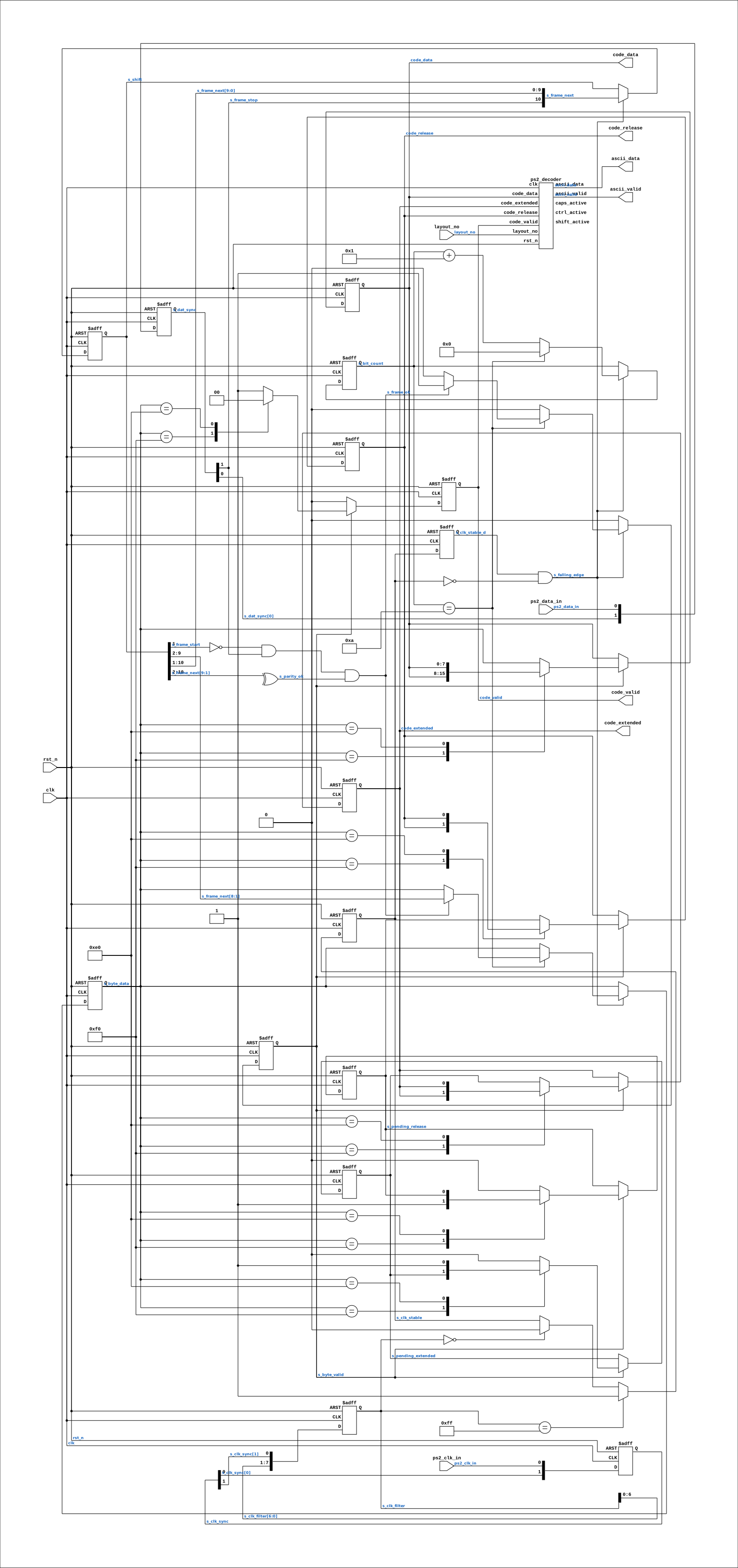
Drawn from the Verilog: no build top uses this module, so it was elaborated from its own file with no defines and default parameters. Sub-modules are boxes (click the picture to open it full size; there every sub-module box links to its page, and every wire shows its Verilog name).
Parameters
| Parameter | Default |
|---|---|
FILTER_LEN |
8 |
Ports
| Direction | Width | Name | Description |
|---|---|---|---|
| input | 1 |
clk |
system clock (the pixel clock in our builds) |
| input | 1 |
rst_n (active low) |
async reset, active low |
| input | 1 |
ps2_clk_in |
PS/2 clock from the keyboard |
| input | 1 |
ps2_data_in |
PS/2 data from the keyboard |
| input | 1 |
layout_no |
0 = US ANSI, 1 = Norwegian - see ps2_decoder.v |
| output | 1 |
ascii_valid |
one clock per decoded character |
| output | [7:0] |
ascii_data |
the character |
| output | 1 |
code_valid |
one clock per received scancode byte |
| output | [7:0] |
code_data |
|
| output | 1 |
code_release |
that scancode was a key RELEASE |
| output | 1 |
code_extended |
that scancode had the E0 prefix |
Verilog source
Verilog/Terminals/rtl/ps2_keyboard.v on GitHub.
Show the Verilog of ps2_keyboard (231 lines)
//============================================================================
//! PS/2 keyboard receiver + scancode-set-2 to ASCII decoder
//!
//! Part of the board-independent terminal core (Verilog/Terminals/).
//!
//! Receive-only: this reads the keyboard, it never writes to it (no LED
//! updates, no typematic-rate programming). A keyboard powers up in scancode
//! set 2 with sensible repeat settings, which is all a console needs.
//!
//! WHY PS/2 ON BOARDS WITH USB: neither of our targets makes us write a USB
//! stack. On the Nexys 4 DDR the onboard microcontroller is the USB host and
//! presents the FPGA a plain PS/2 clock/data pair (the board's master XDC
//! literally heads that section "##USB HID (PS/2)", pins F4/B2). On MiSTer,
//! Linux does the USB work and hps_io hands over `ps2_key`. Same protocol,
//! two different machines doing the hard part for us.
//!
//! PROTOCOL: the keyboard drives the clock. Each frame is 11 bits, sampled on
//! the FALLING edge of ps2_clk: start bit (0), 8 data bits LSB first, odd
//! parity, stop bit (1). A frame that fails parity or framing is DROPPED - a
//! corrupted scancode that reaches the decoder can leave the shift state stuck
//! on, which is far worse than a missed keystroke.
//!
//! DECODING: 0xF0 prefixes a key RELEASE, 0xE0 prefixes an EXTENDED key. So
//! "release left shift" arrives as F0 12, and a right-arrow press as E0 74.
//! Modifier state is tracked; everything else is looked up.
//!
//! !! THE ASCII TABLE IS TRANSCRIBED FROM THE PUBLISHED SET-2 TABLES AND HAS
//! !! NOT BEEN CHECKED AGAINST A PHYSICAL KEYBOARD. The testbench proves the
//! !! protocol and the state machine, not the table. Checking the table is
//! !! exactly phase 3 of fpga/nexys4ddr/PLAN-vga-console.md - type on a real
//! !! keyboard and read the screen. Treat every entry as a claim until then.
//!
//! Written 27-AUG-2026.
//============================================================================

`default_nettype none

module ps2_keyboard #(
    //! Clocks to hold the PS/2 lines stable before believing them. The PS/2
    //! clock is 10-16.7 kHz, so at 40 MHz a bit lasts >2400 clocks - filtering
    //! 8 of them is nothing, and it kills the contact noise that otherwise
    //! shows up as doubled characters.
    parameter integer FILTER_LEN = 8
) (
    input wire clk,    //! system clock (the pixel clock in our builds)
    input wire rst_n,  //! async reset, active low

    input wire ps2_clk_in,   //! PS/2 clock from the keyboard
    input wire ps2_data_in,  //! PS/2 data from the keyboard

    input wire layout_no,    //! 0 = US ANSI, 1 = Norwegian - see ps2_decoder.v

    output wire       ascii_valid,  //! one clock per decoded character
    output wire [7:0] ascii_data,   //! the character

    // Raw scancode stream, for debugging and for the TDV work later, where the
    // mapping is by key rather than by character.
    output reg       code_valid,   //! one clock per received scancode byte
    output reg [7:0] code_data,
    output reg       code_release, //! that scancode was a key RELEASE
    output reg       code_extended //! that scancode had the E0 prefix
);

  //--------------------------------------------------------------------------
  // Input conditioning: synchronize, then require FILTER_LEN stable samples
  //--------------------------------------------------------------------------

  reg [1:0] s_clk_sync;
  reg [1:0] s_dat_sync;

  reg [FILTER_LEN-1:0] s_clk_filter;
  reg                  s_clk_stable;
  reg                  s_clk_stable_d;

  always @(posedge clk or negedge rst_n) begin
    if (!rst_n) begin
      s_clk_sync     <= 2'b11;
      s_dat_sync     <= 2'b11;
      s_clk_filter   <= {FILTER_LEN{1'b1}};
      s_clk_stable   <= 1'b1;
      s_clk_stable_d <= 1'b1;
    end else begin
      s_clk_sync <= {s_clk_sync[0], ps2_clk_in};
      s_dat_sync <= {s_dat_sync[0], ps2_data_in};

      s_clk_filter <= {s_clk_filter[FILTER_LEN-2:0], s_clk_sync[1]};

      // Only move when every sample in the window agrees.
      if (s_clk_filter == {FILTER_LEN{1'b1}}) s_clk_stable <= 1'b1;
      else if (s_clk_filter == {FILTER_LEN{1'b0}}) s_clk_stable <= 1'b0;

      s_clk_stable_d <= s_clk_stable;
    end
  end

  //! The keyboard puts data on the line before this edge, so this is where it
  //! is safe to sample.
  wire s_falling_edge = s_clk_stable_d && !s_clk_stable;

  //--------------------------------------------------------------------------
  // Frame receiver - 11 bits, LSB first
  //--------------------------------------------------------------------------

  reg  [3:0] s_bit_count;
  reg [10:0] s_shift;

  //! The frame as it WILL be once this bit is shifted in - bits arrive LSB
  //! first into the top of the register, so after 11 shifts bit 0 is the start
  //! bit and bit 10 is the stop bit. Named as a wire because a concatenation
  //! cannot be part-selected directly.
  wire [10:0] s_frame_next = {s_dat_sync[1], s_shift[10:1]};

  wire s_frame_start  = s_frame_next[0];
  wire s_frame_stop   = s_frame_next[10];
  //! Odd parity: the 8 data bits plus the parity bit must XOR to 1.
  wire s_parity_ok    = (^s_frame_next[9:1]) == 1'b1;
  wire s_frame_ok     = (s_frame_start == 1'b0) && (s_frame_stop == 1'b1) && s_parity_ok;

  reg s_byte_valid;
  reg [7:0] s_byte_data;

  always @(posedge clk or negedge rst_n) begin
    if (!rst_n) begin
      s_bit_count  <= 4'd0;
      s_shift      <= 11'd0;
      s_byte_valid <= 1'b0;
      s_byte_data  <= 8'h00;
    end else begin
      s_byte_valid <= 1'b0;

      if (s_falling_edge) begin
        s_shift <= s_frame_next;

        if (s_bit_count == 4'd10) begin
          s_bit_count <= 4'd0;
          // A bad frame is dropped silently. A corrupted scancode that reaches
          // the decoder can leave shift or ctrl stuck on, which is worse than
          // losing the keystroke.
          if (s_frame_ok) begin
            s_byte_valid <= 1'b1;
            s_byte_data  <= s_frame_next[8:1];
          end
        end else begin
          s_bit_count <= s_bit_count + 4'd1;
        end
      end
    end
  end

  //--------------------------------------------------------------------------
  // Prefix handling - E0 (extended) and F0 (release)
  //
  // This is all that is left here after the 28-AUG-2026 split: the framing
  // above and the prefixes here are the parts that only exist because this
  // board hands us a raw serial line. Everything with actual keyboard logic in
  // it - modifiers, caps lock, control characters, the TDV cursor keys - moved
  // to ps2_decoder.v so that MiSTer, whose scancodes arrive already framed
  // from Linux, shares it rather than carrying a second copy that can drift.
  //--------------------------------------------------------------------------

  localparam [7:0] SC_RELEASE  = 8'hF0;
  localparam [7:0] SC_EXTENDED = 8'hE0;

  reg s_pending_release;
  reg s_pending_extended;

  always @(posedge clk or negedge rst_n) begin
    if (!rst_n) begin
      s_pending_release  <= 1'b0;
      s_pending_extended <= 1'b0;
      code_valid         <= 1'b0;
      code_data          <= 8'h00;
      code_release       <= 1'b0;
      code_extended      <= 1'b0;
    end else begin
      code_valid <= 1'b0;

      if (s_byte_valid) begin
        case (s_byte_data)
          SC_RELEASE:  s_pending_release  <= 1'b1;
          SC_EXTENDED: s_pending_extended <= 1'b1;

          default: begin
            // Every non-prefix byte ends a scancode, so publish the raw one
            // and clear the prefixes no matter what it turns out to be.
            code_valid    <= 1'b1;
            code_data     <= s_byte_data;
            code_release  <= s_pending_release;
            code_extended <= s_pending_extended;

            s_pending_release  <= 1'b0;
            s_pending_extended <= 1'b0;
          end
        endcase
      end
    end
  end

  //--------------------------------------------------------------------------
  // The shared decoder
  //
  // TIMING NOTE: ascii_valid now lands ONE CLOCK after code_valid, where
  // before the split both were produced by the same always block on the same
  // clock. Nothing downstream cares - the byte goes into a CDC or a UART
  // shift register next, and one 40 MHz clock is 25 ns against a keystroke -
  // but it IS a behaviour change, so it is written down rather than left for
  // someone to rediscover in a waveform.
  //--------------------------------------------------------------------------

  ps2_decoder DECODER (
      .clk  (clk),
      .rst_n(rst_n),

      .code_valid   (code_valid),
      .code_data    (code_data),
      .code_release (code_release),
      .code_extended(code_extended),

      .layout_no(layout_no),

      .ascii_valid(ascii_valid),
      .ascii_data (ascii_data),

      .shift_active(),
      .ctrl_active (),
      .caps_active ()
  );

endmodule

`default_nettype wire