vga_timing
Source: Verilog/Terminals/rtl/vga_timing.v
Where it sits (Nexys): nd120_nexys4ddr_top > terminal_top > text_screen > vga_timing
- instance path: TERMINAL.SCREEN.TIMING
Used in: text_screen (Nexys, MiSTer, MEGA65 R6, MEGA65 R3)
Contains: no other modules.
Module hierarchy - All modules
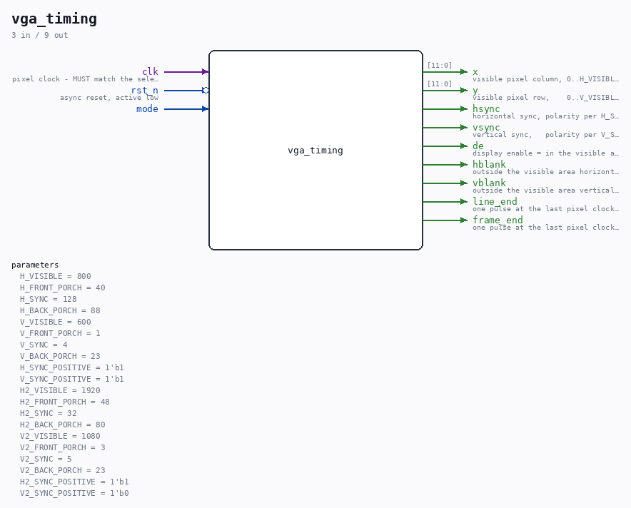
Schematic
Drawn from the Verilog: the yosys netlist of the Nexys 4 DDR build, instance TERMINAL.SCREEN.TIMING. Sub-modules are boxes (click the picture to open it full size; there every sub-module box links to its page, and every wire shows its Verilog name).
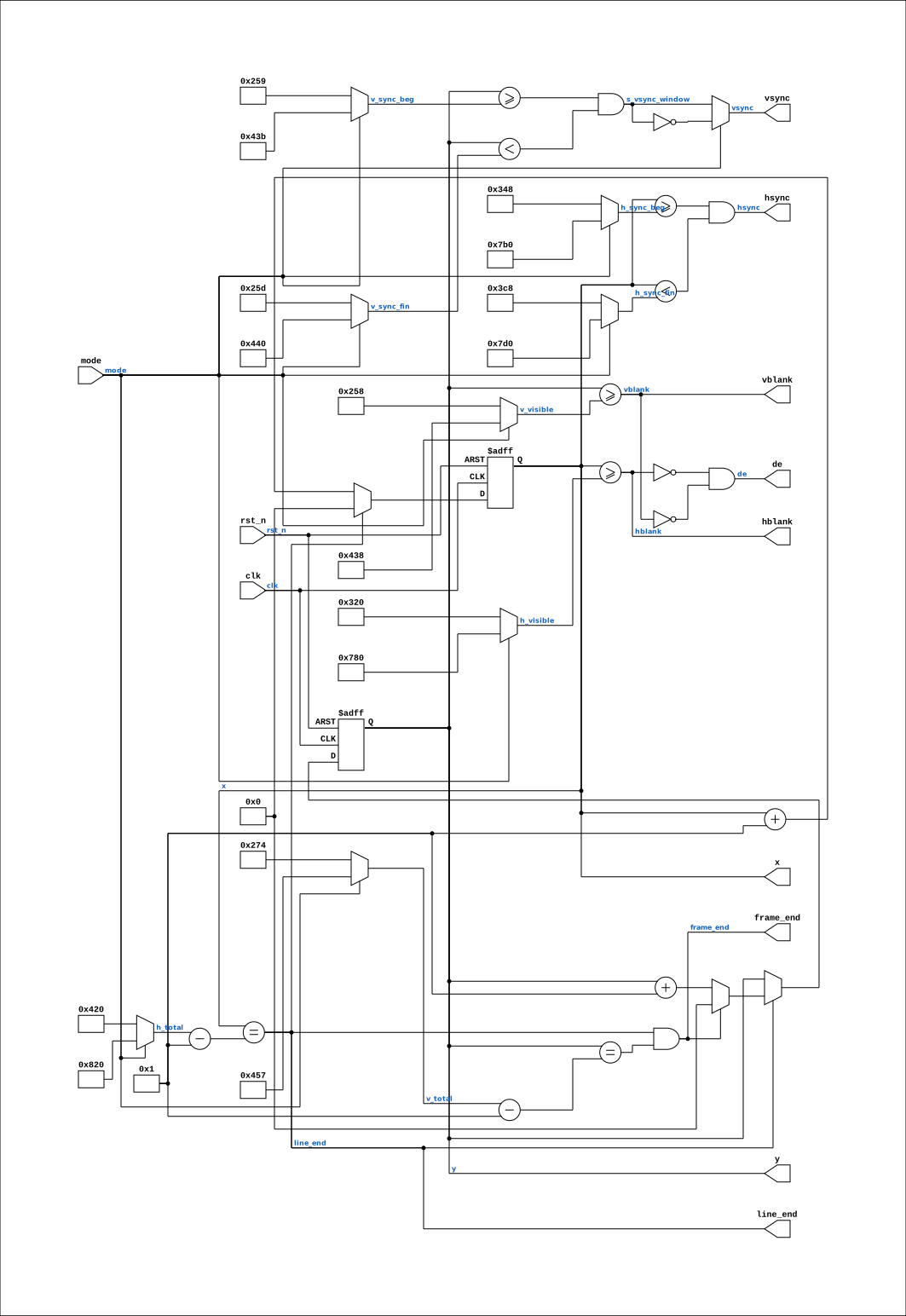
Parameters
| Parameter | Default |
|---|---|
H_VISIBLE |
800 |
H_FRONT_PORCH |
40 |
H_SYNC |
128 |
H_BACK_PORCH |
88 |
V_VISIBLE |
600 |
V_FRONT_PORCH |
1 |
V_SYNC |
4 |
V_BACK_PORCH |
23 |
H_SYNC_POSITIVE |
1'b1 |
V_SYNC_POSITIVE |
1'b1 |
H2_VISIBLE |
1920 |
H2_FRONT_PORCH |
48 |
H2_SYNC |
32 |
H2_BACK_PORCH |
80 |
V2_VISIBLE |
1080 |
V2_FRONT_PORCH |
3 |
V2_SYNC |
5 |
V2_BACK_PORCH |
23 |
H2_SYNC_POSITIVE |
1'b1 |
V2_SYNC_POSITIVE |
1'b0 |
Ports
| Direction | Width | Name | Description |
|---|---|---|---|
| input | 1 |
clk |
pixel clock - MUST match the selected mode |
| input | 1 |
rst_n (active low) |
async reset, active low |
| input | 1 |
mode |
|
| output | [11:0] |
x |
visible pixel column, 0..H_VISIBLE-1 (only valid while de) |
| output | [11:0] |
y |
visible pixel row, 0..V_VISIBLE-1 (only valid while de) |
| output | 1 |
hsync |
horizontal sync, polarity per H_SYNC_POSITIVE |
| output | 1 |
vsync |
vertical sync, polarity per V_SYNC_POSITIVE |
| output | 1 |
de |
display enable = in the visible area (~(hblank|vblank)) |
| output | 1 |
hblank |
outside the visible area horizontally |
| output | 1 |
vblank |
outside the visible area vertically |
| output | 1 |
line_end |
one pulse at the last pixel clock of every line |
| output | 1 |
frame_end |
one pulse at the last pixel clock of every frame |
Verilog source
Verilog/Terminals/rtl/vga_timing.v on GitHub.
Show the Verilog of vga_timing (159 lines)
//============================================================================
//! VGA timing generator - pixel/line counters, sync and blanking
//!
//! Part of the board-independent terminal core (Verilog/Terminals/).
//! Plan: Verilog/Terminals/docs/PLAN-vt100-terminal-core.md
//!
//! Defaults are 800x600 @ 60 Hz, "VESA discrete monitor timing":
//!     pixel clock 40.000 MHz
//!     horizontal  800 visible, 40 front porch, 128 sync, 88 back porch = 1056
//!     vertical    600 visible,  1 front porch,   4 sync,  23 back porch =  628
//!     sync polarity POSITIVE on both H and V
//!     40e6 / (1056 * 628) = 60.32 Hz
//!
//! Why 800x600 and not 640x480: on the Nexys 4 DDR the existing MMCM runs a
//! 1000 MHz VCO, so an integer divide of 25 gives EXACTLY 40.000 MHz. The
//! 640x480 pixel clock (25.175 MHz) is not reachable from that VCO - the
//! closest is 25.000 MHz, 0.7% low. See fpga/nexys4ddr/PLAN-vga-console.md.
//!
//! Everything is a parameter, so a board that wants a different mode changes
//! numbers rather than code.
//!
//! Written 27-AUG-2026.
//============================================================================

`default_nettype none

module vga_timing #(
    // Horizontal, in pixel clocks
    parameter integer H_VISIBLE     = 800,
    parameter integer H_FRONT_PORCH = 40,
    parameter integer H_SYNC        = 128,
    parameter integer H_BACK_PORCH  = 88,

    // Vertical, in lines
    parameter integer V_VISIBLE     = 600,
    parameter integer V_FRONT_PORCH = 1,
    parameter integer V_SYNC        = 4,
    parameter integer V_BACK_PORCH  = 23,

    //! 1 = sync pulse is high while active (800x600 wants positive on both).
    //! 640x480 would want 0 on both - the one thing that changes with the mode
    //! besides the counts.
    parameter         H_SYNC_POSITIVE = 1'b1,
    parameter         V_SYNC_POSITIVE = 1'b1,

    // ------------------------------------------------------------------
    // MODE 1 - a SECOND, runtime-selectable video mode.
    //
    // Defaults are 1920x1080@60 (CEA-861: 148.5 MHz pixel clock, both syncs
    // POSITIVE). The board supplies the matching pixel clock; this module only
    // counts, so it does not know or care what the clock actually is - which is
    // exactly why the mode and the clock must be switched by the same bit.
    // ------------------------------------------------------------------
    parameter integer H2_VISIBLE     = 1920,
    parameter integer H2_FRONT_PORCH = 48,
    parameter integer H2_SYNC        = 32,
    parameter integer H2_BACK_PORCH  = 80,
    parameter integer V2_VISIBLE     = 1080,
    parameter integer V2_FRONT_PORCH = 3,
    parameter integer V2_SYNC        = 5,
    parameter integer V2_BACK_PORCH  = 23,
    //! CVT-RB polarity: hsync POSITIVE, vsync NEGATIVE. Getting this wrong does
    //! not blank the screen, it makes a monitor guess the wrong mode - which
    //! looks like the design being broken.
    parameter         H2_SYNC_POSITIVE = 1'b1,
    parameter         V2_SYNC_POSITIVE = 1'b0
) (
    input wire clk,      //! pixel clock - MUST match the selected mode
    input wire rst_n,    //! async reset, active low

    //! 0 = mode 0 (the H_*/V_* parameters), 1 = mode 1 (H2_*/V2_*).
    //! Change this only together with the pixel clock.
    input wire mode,

    output wire [11:0] x,        //! visible pixel column, 0..H_VISIBLE-1 (only valid while de)
    output wire [11:0] y,        //! visible pixel row,    0..V_VISIBLE-1 (only valid while de)
    output wire        hsync,    //! horizontal sync, polarity per H_SYNC_POSITIVE
    output wire        vsync,    //! vertical sync,   polarity per V_SYNC_POSITIVE
    output wire        de,       //! display enable = in the visible area (~(hblank|vblank))
    output wire        hblank,   //! outside the visible area horizontally
    output wire        vblank,   //! outside the visible area vertically
    output wire        line_end, //! one pulse at the last pixel clock of every line
    output wire        frame_end //! one pulse at the last pixel clock of every frame
);

  localparam integer H_TOTAL = H_VISIBLE + H_FRONT_PORCH + H_SYNC + H_BACK_PORCH;
  localparam integer V_TOTAL = V_VISIBLE + V_FRONT_PORCH + V_SYNC + V_BACK_PORCH;

  // Sync starts after the front porch and lasts H_SYNC / V_SYNC ticks.
  localparam integer H_SYNC_START = H_VISIBLE + H_FRONT_PORCH;
  localparam integer H_SYNC_END   = H_SYNC_START + H_SYNC;
  localparam integer V_SYNC_START = V_VISIBLE + V_FRONT_PORCH;
  localparam integer V_SYNC_END   = V_SYNC_START + V_SYNC;

  localparam integer H2_TOTAL = H2_VISIBLE + H2_FRONT_PORCH + H2_SYNC + H2_BACK_PORCH;
  localparam integer V2_TOTAL = V2_VISIBLE + V2_FRONT_PORCH + V2_SYNC + V2_BACK_PORCH;
  localparam integer H2_SYNC_START = H2_VISIBLE + H2_FRONT_PORCH;
  localparam integer H2_SYNC_END   = H2_SYNC_START + H2_SYNC;
  localparam integer V2_SYNC_START = V2_VISIBLE + V2_FRONT_PORCH;
  localparam integer V2_SYNC_END   = V2_SYNC_START + V2_SYNC;

  //! The counts actually in force. Muxed rather than parameterised, because the
  //! mode is chosen by a switch on the board at run time - the whole point.
  wire [11:0] h_total     = mode ? H2_TOTAL[11:0]       : H_TOTAL[11:0];
  wire [11:0] v_total     = mode ? V2_TOTAL[11:0]       : V_TOTAL[11:0];
  wire [11:0] h_visible   = mode ? H2_VISIBLE[11:0]     : H_VISIBLE[11:0];
  wire [11:0] v_visible   = mode ? V2_VISIBLE[11:0]     : V_VISIBLE[11:0];
  wire [11:0] h_sync_beg  = mode ? H2_SYNC_START[11:0]  : H_SYNC_START[11:0];
  wire [11:0] h_sync_fin  = mode ? H2_SYNC_END[11:0]    : H_SYNC_END[11:0];
  wire [11:0] v_sync_beg  = mode ? V2_SYNC_START[11:0]  : V_SYNC_START[11:0];
  wire [11:0] v_sync_fin  = mode ? V2_SYNC_END[11:0]    : V_SYNC_END[11:0];
  wire        h_sync_pos  = mode ? H2_SYNC_POSITIVE     : H_SYNC_POSITIVE;
  wire        v_sync_pos  = mode ? V2_SYNC_POSITIVE     : V_SYNC_POSITIVE;

  reg [11:0] s_hcount;
  reg [11:0] s_vcount;

  //! last pixel clock of a line / of a frame - used to advance the counters and
  //! exported so the character generator can do its per-line and per-frame work
  //! (cursor blink, row address reload) without re-deriving them.
  assign line_end  = (s_hcount == h_total - 12'd1);
  assign frame_end = line_end && (s_vcount == v_total - 12'd1);

  always @(posedge clk or negedge rst_n) begin
    if (!rst_n) begin
      s_hcount <= 12'd0;
      s_vcount <= 12'd0;
    end else begin
      if (line_end) begin
        s_hcount <= 12'd0;
        s_vcount <= frame_end ? 12'd0 : (s_vcount + 12'd1);
      end else begin
        s_hcount <= s_hcount + 12'd1;
      end
    end
  end

  assign hblank = (s_hcount >= h_visible);
  assign vblank = (s_vcount >= v_visible);
  assign de     = !hblank && !vblank;

  // x and y are only meaningful inside the visible area; outside it they keep
  // counting, which costs nothing and makes the counters easy to watch in a
  // waveform. Consumers must gate on `de`.
  assign x = s_hcount;
  assign y = s_vcount;

  // The raw sync window, then the polarity applied. Kept in two steps because
  // getting the polarity backwards is the classic "monitor says no signal" bug
  // and this way the window itself is readable in a waveform.
  wire s_hsync_window = (s_hcount >= h_sync_beg) && (s_hcount < h_sync_fin);
  wire s_vsync_window = (s_vcount >= v_sync_beg) && (s_vcount < v_sync_fin);

  assign hsync = h_sync_pos ? s_hsync_window : ~s_hsync_window;
  assign vsync = v_sync_pos ? s_vsync_window : ~s_vsync_window;

endmodule

`default_nettype wire