terminal_top
Source: Verilog/Terminals/rtl/terminal_top.v
Where it sits (Nexys): nd120_nexys4ddr_top > terminal_top
- instance path: TERMINAL
Used in: nd120_console_mega65 (MEGA65 R6, MEGA65 R3), nd120_console_mister (MiSTer), nd120_nexys4ddr_top (Nexys)
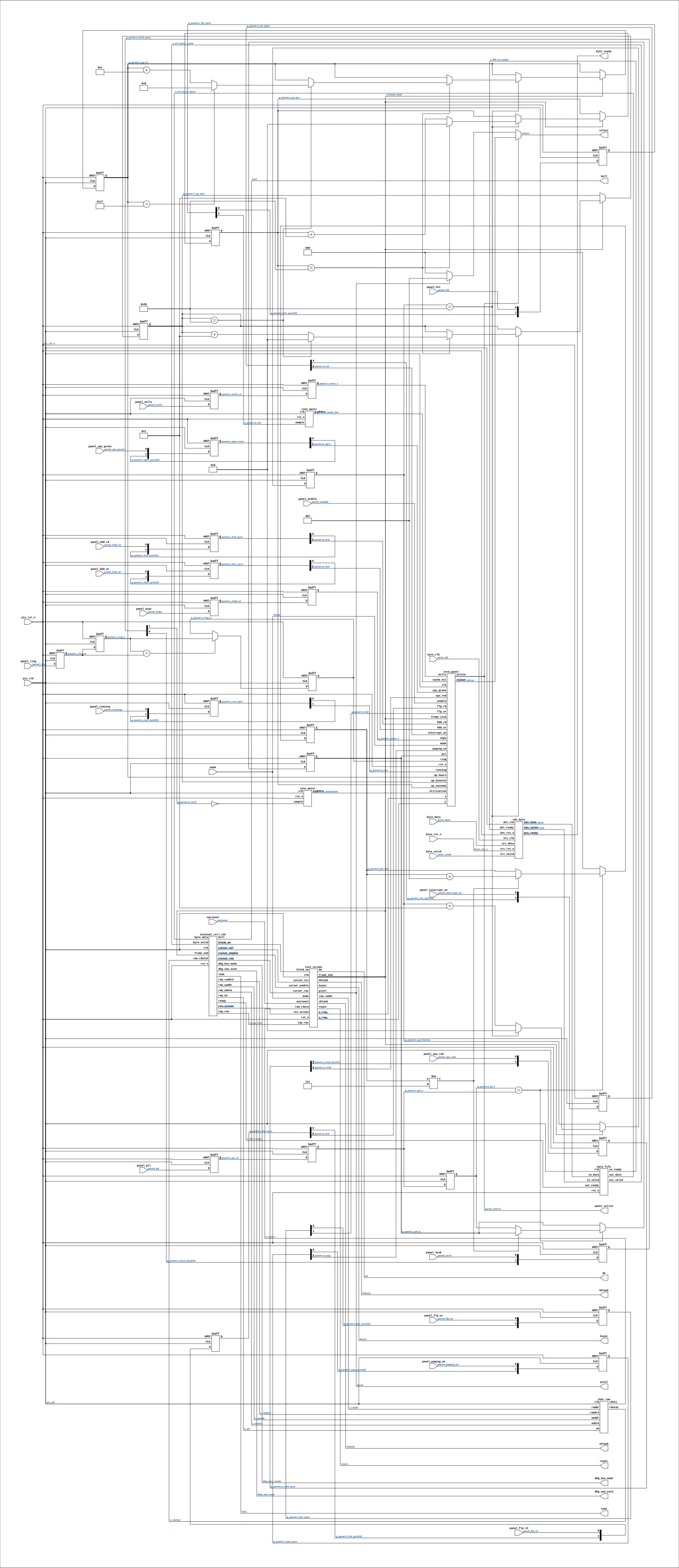
Contains: byte_fifo, cdc_byte, char_ram, rate_meter x2, term_panel, terminal_ctrl_tdv, text_screen
Module hierarchy - All modules
Schematic
Drawn from the Verilog: the yosys netlist of the Nexys 4 DDR build, instance TERMINAL. Sub-modules are boxes (click the picture to open it full size; there every sub-module box links to its page, and every wire shows its Verilog name).
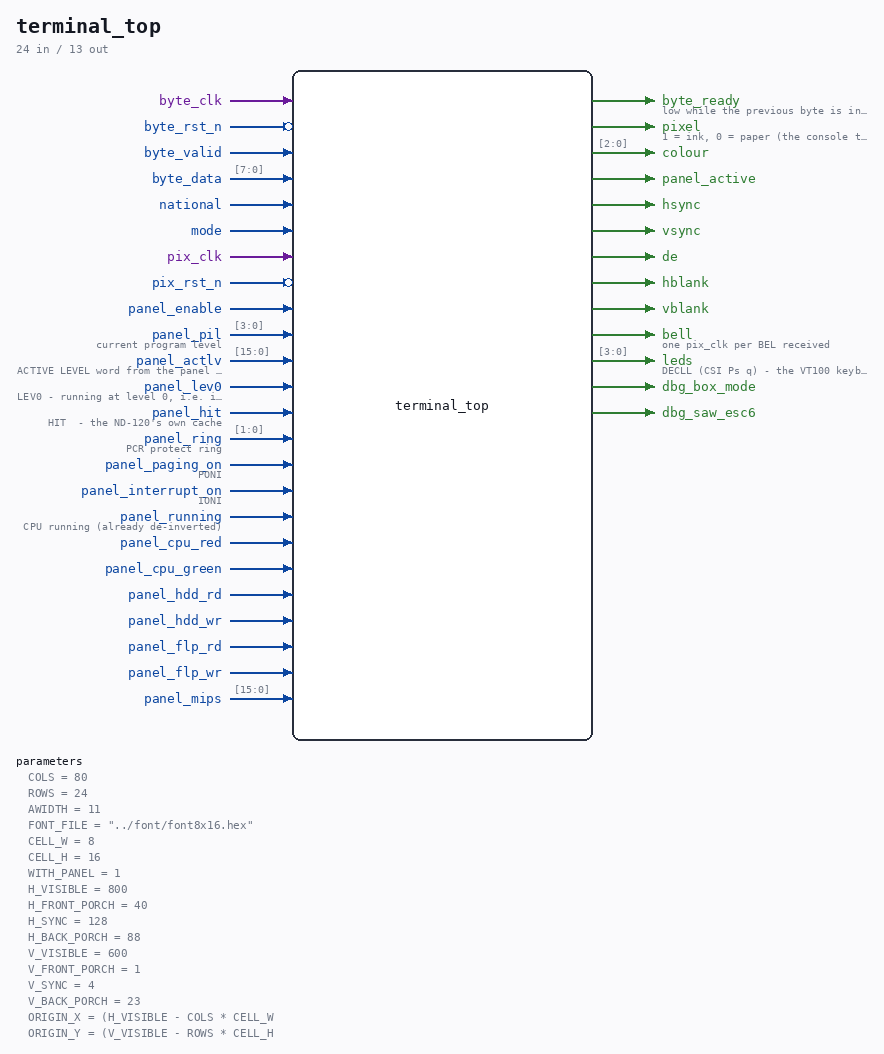
Parameters
| Parameter | Default |
|---|---|
COLS |
80 |
ROWS |
24 |
AWIDTH |
11 |
FONT_FILE |
"../font/font8x16.hex" |
CELL_W |
8 |
CELL_H |
16 |
WITH_PANEL |
1 |
H_VISIBLE |
800 |
H_FRONT_PORCH |
40 |
H_SYNC |
128 |
H_BACK_PORCH |
88 |
V_VISIBLE |
600 |
V_FRONT_PORCH |
1 |
V_SYNC |
4 |
V_BACK_PORCH |
23 |
ORIGIN_X |
(H_VISIBLE - COLS * CELL_W |
ORIGIN_Y |
(V_VISIBLE - ROWS * CELL_H |
Ports
| Direction | Width | Name | Description |
|---|---|---|---|
| input | 1 |
byte_clk |
|
| input | 1 |
byte_rst_n (active low) |
|
| input | 1 |
byte_valid |
|
| input | [7:0] |
byte_data |
|
| output | 1 |
byte_ready |
low while the previous byte is in flight |
| input | 1 |
national |
|
| input | 1 |
mode |
|
| input | 1 |
pix_clk |
|
| input | 1 |
pix_rst_n (active low) |
|
| output | 1 |
pixel |
1 = ink, 0 = paper (the console text alone) |
| output | [2:0] |
colour |
|
| output | 1 |
panel_active |
|
| output | 1 |
hsync |
|
| output | 1 |
vsync |
|
| output | 1 |
de |
|
| output | 1 |
hblank |
|
| output | 1 |
vblank |
|
| input | 1 |
panel_enable |
|
| input | [3:0] |
panel_pil |
current program level |
| input | [15:0] |
panel_actlv |
ACTIVE LEVEL word from the panel processor (0 = none yet) |
| input | 1 |
panel_lev0 |
LEV0 - running at level 0, i.e. idle |
| input | 1 |
panel_hit |
HIT - the ND-120's own cache |
| input | [1:0] |
panel_ring |
PCR protect ring |
| input | 1 |
panel_paging_on |
PONI |
| input | 1 |
panel_interrupt_on |
IONI |
| input | 1 |
panel_running |
CPU running (already de-inverted) |
| input | 1 |
panel_cpu_red |
|
| input | 1 |
panel_cpu_green |
|
| input | 1 |
panel_hdd_rd |
|
| input | 1 |
panel_hdd_wr |
|
| input | 1 |
panel_flp_rd |
|
| input | 1 |
panel_flp_wr |
|
| input | [15:0] |
panel_mips |
|
| output | 1 |
bell |
one pix_clk per BEL received |
| output | [3:0] |
leds |
DECLL (CSI Ps q) - the VT100 keyboard lamps L1-L4 |
| output | 1 |
dbg_box_mode |
|
| output | 1 |
dbg_saw_esc6 |
Verilog source
Verilog/Terminals/rtl/terminal_top.v on GitHub.
Show the Verilog of terminal_top (643 lines)
//============================================================================
//! Terminal core - top level. Bytes in, video out.
//!
//! Part of the board-independent terminal core (Verilog/Terminals/).
//! Plan: Verilog/Terminals/docs/PLAN-vt100-terminal-core.md
//!
//! This is the whole Stage A terminal: give it console bytes on any clock and
//! it gives you a monochrome pixel stream with sync. It knows nothing about
//! any board - no VGA connector, no HDMI scaler, no keyboard. Each board wires
//! the two ends:
//!
//!   Nexys 4 DDR : deserialize cpu_txd into byte_in; pixel -> the 12-bit VGA
//!                 pins; keyboard from the onboard USB host as plain PS/2
//!   MiSTer      : ps2_key from hps_io; pixel -> CLK_VIDEO/CE_PIXEL/VGA_*
//!   MEGA65      : mega65 keyboard matrix; pixel -> the VDAC
//!
//! Keyboard input is NOT handled here - a keyboard produces bytes that go back
//! to the machine, which is the board's business, not the screen's.
//!
//! Written 27-AUG-2026.
//============================================================================

`default_nettype none

module terminal_top #(
    parameter integer COLS      = 80,
    parameter integer ROWS      = 24,
    parameter integer AWIDTH    = 11,
    parameter         FONT_FILE = "../font/font8x16.hex",

    //! Glyph box. Set by the font, not a free choice - font8x16.hex is 8 wide
    //! and 16 tall. Parameters here only so the origins below can be derived
    //! from them; change the font before changing these.
    parameter integer CELL_W = 8,
    parameter integer CELL_H = 16,

    //! 0 removes the operator panel from the design ENTIRELY - the renderer,
    //! its font ROM, the rate meters and the uptime counter all disappear.
    //!
    //! This is NOT the same as the board's panel switch. That switch blanks the
    //! panel at run time and the logic stays in the bitstream; this parameter is
    //! what you reach for when fabric or timing is actually tight. Both exist
    //! because they answer different questions.
    parameter integer WITH_PANEL = 1,

    // VGA mode - defaults are 800x600@60 from a 40.000 MHz pixel clock
    parameter integer H_VISIBLE     = 800,
    parameter integer H_FRONT_PORCH = 40,
    parameter integer H_SYNC        = 128,
    parameter integer H_BACK_PORCH  = 88,
    parameter integer V_VISIBLE     = 600,
    parameter integer V_FRONT_PORCH = 1,
    parameter integer V_SYNC        = 4,
    parameter integer V_BACK_PORCH  = 23,
    //! Top-left corner of the character grid inside the visible area.
    //!
    //! COMPUTED, not written down, and that is the point. These were constants
    //! until 28-AUG-2026, and ORIGIN_Y still said 108 - the value that centres
    //! a 24-ROW grid - long after the terminal became the TDV2200's real
    //! 80x25. It was not harmless: terminal_top passes its OWN defaults down,
    //! so 108 OVERRODE the corrected 100 in text_screen.v, and no board
    //! overrides it, so every build would have drawn the grid 8 pixels low.
    //!
    //! text_screen_tb did not catch it because it passes 100 explicitly - a
    //! test that supplies its own value cannot check a default. Deriving the
    //! number from the ones it depends on removes the whole failure mode:
    //! change ROWS, COLS or the video mode and the grid re-centres itself.
    parameter integer ORIGIN_X      = (H_VISIBLE - COLS * CELL_W) / 2,
    parameter integer ORIGIN_Y      = (V_VISIBLE - ROWS * CELL_H) / 2
) (
    // Byte in - the console stream, on ITS OWN clock
    input  wire       byte_clk,
    input  wire       byte_rst_n,
    input  wire       byte_valid,
    input  wire [7:0] byte_data,
    output wire       byte_ready,  //! low while the previous byte is in flight

    //! Font page: 0 = US / ISO 646 IRV, 1 = Norwegian (NS 4551-1). Must be
    //! driven from the SAME source as the keyboard's layout_no - the two
    //! disagreeing is worse than either being wrong, because what you type and
    //! what you see stop matching.
    input  wire national,

    //! Video mode: 0 = the H_*/V_* parameters at 1x glyphs, 1 = H2_*/V2_* at
    //! 2x. The board MUST switch the pixel clock with it - this core only
    //! counts, it cannot know what the clock really is.
    input  wire mode,

    // Video out - pixel clock domain
    input  wire pix_clk,
    input  wire pix_rst_n,
    output wire pixel,   //! 1 = ink, 0 = paper (the console text alone)

    //! Palette index for this pixel. The BOARD maps it to its own colour
    //! depth, so nothing board-specific lives in this core:
    //!   0 black  1 text ink  2 fascia  3 silkscreen
    //!   4 LCD ground  5 LCD segment  6 lit legend  7 unlit legend
    output wire [2:0] colour,
    //! 1 while this pixel belongs to the operator panel (not the console text
    //! or banner). A board that lets the user recolour the console-text
    //! palette index can gate on this so the panel's own green CPU lamp,
    //! which uses the same index, stays fixed. Safe to leave unconnected.
    output wire       panel_active,
    output wire hsync,
    output wire vsync,
    output wire de,
    //! `de` split in two, for a board whose framework wants them separately
    //! (MiSTer2MEGA65). Same two-clock alignment as `de`. Added 02-SEP-2026;
    //! leave unconnected where only `de` is needed.
    output wire hblank,
    output wire vblank,

    //! ---- operator panel -------------------------------------------------
    //! Drawn in the empty area below the text grid. `panel_enable` low draws
    //! nothing; it does NOT remove the logic, which is a build-time choice.
    //! RAW machine signals, exactly as they leave ND3202D's DBG_PANEL port in
    //! MC68705 Port-D order. The rate meters and the uptime counter live in
    //! here rather than in each board's top level, so three boards cannot end
    //! up with three slightly different definitions of "utilization".
    input  wire       panel_enable,
    input  wire [3:0] panel_pil,        //! current program level
    input  wire [15:0] panel_actlv,     //! ACTIVE LEVEL word from the panel processor (0 = none yet)
    input  wire       panel_lev0,       //! LEV0 - running at level 0, i.e. idle
    input  wire       panel_hit,        //! HIT  - the ND-120's own cache
    //! High while the lookup HIT belongs to is happening. Without it there is
    //! no denominator and the CACHE HIT RATE bar cannot mean anything.

    input  wire [1:0] panel_ring,       //! PCR protect ring
    input  wire       panel_paging_on,  //! PONI
    input  wire       panel_interrupt_on, //! IONI
    input  wire       panel_running,    //! CPU running (already de-inverted)

    //! Disc access strobes - Winchester and floppy, read and write. Held and
    //! displayed by the panel; see term_panel.v.
    //! CPU board lamps - LED[0] RED (MACL in progress) and LED[1] GREEN
    //! (initialisation complete, written only at MACL2 = self-test passed).
    input  wire       panel_cpu_red,
    input  wire       panel_cpu_green,
    input  wire       panel_hdd_rd,
    input  wire       panel_hdd_wr,
    input  wire       panel_flp_rd,
    input  wire       panel_flp_wr,

    //! MIPS word from the board's mips_counter (CPU clock domain), {d3,d2,
    //! d1,d0} BCD. Boards without a counter tie it to 0 and the panel shows
    //! 00.00. Synced below exactly as ACTLV is.
    input  wire [15:0] panel_mips,

    output wire bell,       //! one pix_clk per BEL received
    output wire [3:0] leds, //! DECLL (CSI Ps q) - the VT100 keyboard lamps L1-L4

    //! Box-charset debug taps (01-SEP-2026, TDV only - tied 0 on VT100,
    //! which has no NDSS6 concept). See terminal_ctrl_tdv.v's port comment.
    output wire dbg_box_mode,
    output wire dbg_saw_esc6
);

  //--------------------------------------------------------------------------
  // Byte into the pixel domain
  //--------------------------------------------------------------------------

  wire       s_pix_byte_valid;
  wire [7:0] s_pix_byte_data;
  wire       s_fifo_in_ready;
  wire       s_ctrl_byte_valid;
  wire [7:0] s_ctrl_byte_data;
  //! terminal_ctrl is not always able to take a byte - a clear-screen sweep
  //! walks 1920 cells and a DECSTBM region scroll ~3.8k clocks, holding this
  //! low throughout. See the CDC note and byte_fifo.v.
  wire       s_ctrl_ready;

  cdc_byte CDC (
      .src_clk  (byte_clk),
      .src_rst_n(byte_rst_n),
      .src_valid(byte_valid),
      .src_data (byte_data),
      .src_ready(byte_ready),

      .dst_clk  (pix_clk),
      .dst_rst_n(pix_rst_n),
      .dst_valid(s_pix_byte_valid),
      .dst_data (s_pix_byte_data),
      .dst_ready(s_fifo_in_ready)
  );

  //! Elastic buffer between the crossing and the controller. A VT100 region
  //! scroll runs ~96 us at 40 MHz - longer than one 115200-baud byte time -
  //! and the console UART receiver does not respect ready, so without slack
  //! here a byte arriving mid-scroll would be lost. See byte_fifo.v.
  byte_fifo FIFO (
      .clk      (pix_clk),
      .rst_n    (pix_rst_n),
      .in_valid (s_pix_byte_valid),
      .in_data  (s_pix_byte_data),
      .in_ready (s_fifo_in_ready),
      .out_valid(s_ctrl_byte_valid),
      .out_data (s_ctrl_byte_data),
      .out_ready(s_ctrl_ready)
  );

  //--------------------------------------------------------------------------
  // Character RAM - written by the control logic, read by the screen
  //--------------------------------------------------------------------------

  wire              s_we;
  wire [AWIDTH-1:0] s_waddr;
  wire [      15:0] s_wdata;
  wire [AWIDTH-1:0] s_raddr;
  wire [      15:0] s_rdata;
  wire [AWIDTH-1:0] s_raddr2;
  wire [      15:0] s_rdata2;

  char_ram #(
      .COLS  (COLS),
      .ROWS  (ROWS),
      .AWIDTH(AWIDTH)
  ) CHARRAM (
      .clk   (pix_clk),
      .we    (s_we),
      .waddr (s_waddr),
      .wdata (s_wdata),
      .raddr2(s_raddr2),
      .rdata2(s_rdata2),
      .raddr (s_raddr),
      .rdata (s_rdata)
  );

  //--------------------------------------------------------------------------
  // Screen state
  //--------------------------------------------------------------------------

  wire [7:0] s_top_row;
  wire [7:0] s_cursor_col;
  wire [7:0] s_cursor_row;
  wire       s_cursor_enable;
  wire       s_frame_end;
  wire       s_rev_screen;
  wire       s_blink_on;

  // Two separate, compile-time-selected controllers - VT100 (type 6) and
  // TDV2200 (type 93), never both in the same build. Default TDV2200: PED
  // and LED are built for the Tandberg keyboard's own key set, not VT100
  // CSI sequences (Verilog/Terminals/docs/SPEC-tdv2200.md has the full
  // account of why). Build with -DND120_TERMINAL_VT100 for the VT100
  // variant instead. Same port list either way - only the module name (and
  // the caller's ROWS, 24 vs 25) differs, so this is the one place that
  // needs to know which one exists.
`ifdef ND120_TERMINAL_VT100
  assign dbg_box_mode  = 1'b0;
  assign dbg_saw_esc6  = 1'b0;
  terminal_ctrl #(
      .COLS  (COLS),
      .ROWS  (ROWS),
      .AWIDTH(AWIDTH)
  ) CTRL (
`else
  terminal_ctrl_tdv #(
      .COLS  (COLS),
      .ROWS  (ROWS),
      .AWIDTH(AWIDTH)
  ) CTRL (
      .dbg_box_mode(dbg_box_mode),
      .dbg_saw_esc6(dbg_saw_esc6),
`endif
      .clk  (pix_clk),
      .rst_n(pix_rst_n),

      .byte_valid(s_ctrl_byte_valid),
      .byte_data (s_ctrl_byte_data),
      // FED BACK, since 28-AUG-2026 (and since 30-AUG through the FIFO). This
      // used to be left unconnected on the argument that a 115200 console
      // byte (every ~87 us) could never catch the ~48 us clear-screen window.
      // True of a UART, and false the moment term_banner.v became a source:
      // it hands over a byte every ~150 ns and the power-on clear ate the
      // entire startup message.
      .ready     (s_ctrl_ready),

      .ram_we    (s_we),
      .ram_waddr (s_waddr),
      .ram_wdata (s_wdata),
      .ram_raddr2(s_raddr2),
      .ram_rdata2(s_rdata2),

      .top_row      (s_top_row),
      .cursor_col   (s_cursor_col),
      .cursor_row   (s_cursor_row),
      .cursor_enable(s_cursor_enable),
      .rev_screen   (s_rev_screen),
      .blink_on     (s_blink_on),

      .frame_end(s_frame_end),
      .bell     (bell),
      .leds     (leds)
  );

  wire s_screen_pixel;
  assign pixel = s_screen_pixel;

  //! The panel works from the raw counters and applies its own two clocks of
  //! delay, matching the text pipeline. It never overlaps the text grid, so
  //! there is no arbitration - just a priority in the final mux.
  wire [11:0] s_x_raw, s_y_raw;
  wire        s_panel_active;
  wire [2:0]  s_panel_colour;

  generate
    if (WITH_PANEL != 0) begin : g_panel
    //------------------------------------------------------------------
    // CLOCK-DOMAIN CROSSING for every panel signal
    //
    // These all come from the CPU clock domain and are sampled here in the
    // PIXEL domain. Reading them directly - which is what this did until
    // 28-AUG-2026 - is a genuine CDC violation, and PIL showed exactly why.
    //
    // PIL is four bits that change together. Sampled asynchronously they
    // arrive SKEWED, so a transition like 7 -> 8 (0111 -> 1000) is seen as
    // whatever intermediate codes the individual bits happen to produce -
    // including 1111. That transient got latched into the afterglow and lit
    // level 15, on a machine that never uses level 15. Reported from hardware
    // as "level 15 lights a lot and level 15 is NEVER used", which is precisely
    // what a skewed multi-bit crossing looks like once something downstream
    // remembers what it saw.
    //
    // Two flops for metastability, then - for the multi-bit bus - a stability
    // gate: a value is only accepted once it has held still for a while.
    //
    // TWO SAMPLES WAS NOT ENOUGH - 28-AUG-2026. The first version accepted a
    // value as soon as two consecutive samples agreed, and compared one of
    // them against s_pil_m, the FIRST flop of the synchroniser, which is the
    // one allowed to be metastable. Comparing against a metastable flop is not
    // a stability test at all.
    //
    // It also could not reject what PIL actually does. PIL is STS[11:8]
    // (CGA_ALU.v:134) - the level field of a status register that is selected
    // PER LEVEL, so on a level change the bus settles through intermediate
    // codes before it lands. At 40 MHz pixel clock against a 16.67 MHz CPU
    // clock, one CPU cycle of transient spans about 2.4 pixel samples, which
    // walks straight through a two-sample gate. Downstream, term_panel USED TO
    // reload an afterglow counter for pil on EVERY clock, so a single transient
    // code lit that lamp for the whole ~1 s afterglow. Ronny's report -
    // levels walking 2,3,4,5,6 and "every time the level changes all the
    // levels light up" - looked like exactly that shape.
    //
    // So: three flops, the comparison taken between the SECOND and THIRD (both
    // past the metastable one), and the value accepted only after it has been
    // identical for 8 consecutive samples - 200 ns at 40 MHz, comfortably
    // longer than a CPU cycle. Any code the bus merely passes through on its
    // way somewhere else is discarded.
    //
    // MEASURED ON HARDWARE 29-AUG-2026, AND IT WAS NOT THE CAUSE. Two ILA
    // captures of s_ila_pil on the Nexys (TPE INSTRUCTION test) show a level
    // change as ONE clean transition with no intermediate codes - the bus is
    // fine. What the captures did show is PIL genuinely pulsing to 12, 13,
    // 14, 15 for 15 CPU clocks each (~1 us), and the 63-frame afterglow in
    // term_panel stretched each 1 us blip into a lamp lit for a second. That
    // afterglow is gone - term_panel now shows per-frame occupancy. This gate
    // stays because it is harmless and the reasoning above about a transient
    // code is still sound for a bus that does glitch; it just fixes nothing
    // here.
    //------------------------------------------------------------------
    localparam [2:0] PIL_STABLE_SAMPLES = 3'd7;   //! 8 samples: 0..7

    reg [3:0] s_pil_m, s_pil_s, s_pil_t, s_pil_q;
    reg [2:0] s_pil_cnt;
    reg [1:0] s_lev0_sync, s_hit_sync;
    reg [1:0] s_pag_sync, s_int_sync, s_run_sync;
    reg [1:0] s_hrd_sync, s_hwr_sync, s_frd_sync, s_fwr_sync;
    reg [1:0] s_cred_sync, s_cgrn_sync;
    reg [1:0] s_ring_m, s_ring_s, s_ring_q;

    always @(posedge pix_clk or negedge pix_rst_n) begin
      if (!pix_rst_n) begin
        s_pil_m <= 4'd0; s_pil_s <= 4'd0; s_pil_t <= 4'd0; s_pil_q <= 4'd0;
        s_pil_cnt <= 3'd0;
        s_ring_m <= 2'd0; s_ring_s <= 2'd0; s_ring_q <= 2'd0;
        s_lev0_sync <= 2'd0; s_hit_sync <= 2'd0;
        s_pag_sync  <= 2'd0; s_int_sync <= 2'd0; s_run_sync  <= 2'd0;
        s_cred_sync <= 2'd0; s_cgrn_sync <= 2'd0;
        s_hrd_sync  <= 2'd0; s_hwr_sync <= 2'd0;
        s_frd_sync  <= 2'd0; s_fwr_sync <= 2'd0;
      end else begin
        s_pil_m <= panel_pil;
        s_pil_s <= s_pil_m;
        s_pil_t <= s_pil_s;
        //! Compare the two flops PAST the metastable one, and only publish a
        //! value that has survived 8 consecutive identical samples.
        if (s_pil_t == s_pil_s) begin
          if (s_pil_cnt != PIL_STABLE_SAMPLES) s_pil_cnt <= s_pil_cnt + 3'd1;
          else                                 s_pil_q   <= s_pil_t;
        end else begin
          s_pil_cnt <= 3'd0;
        end

        s_ring_m <= panel_ring;
        s_ring_s <= s_ring_m;
        if (s_ring_s == s_ring_m) s_ring_q <= s_ring_s;

        s_lev0_sync <= {s_lev0_sync[0], panel_lev0};
        s_hit_sync  <= {s_hit_sync[0],  panel_hit};
        s_pag_sync  <= {s_pag_sync[0],  panel_paging_on};
        s_int_sync  <= {s_int_sync[0],  panel_interrupt_on};
        s_run_sync  <= {s_run_sync[0],  panel_running};
        s_cred_sync <= {s_cred_sync[0], panel_cpu_red};
        s_cgrn_sync <= {s_cgrn_sync[0], panel_cpu_green};
        s_hrd_sync  <= {s_hrd_sync[0],  panel_hdd_rd};
        s_hwr_sync  <= {s_hwr_sync[0],  panel_hdd_wr};
        s_frd_sync  <= {s_frd_sync[0],  panel_flp_rd};
        s_fwr_sync  <= {s_fwr_sync[0],  panel_flp_wr};
      end
    end

    wire [3:0] w_pil  = s_pil_q;

    // ACTLV crosses from the CPU clock too. It is a 16-bit word that changes
    // every 20 ms, so plain two-flop synchronisers per bit are enough: a bit
    // caught mid-change is right on the next frame anyway.
    reg [15:0] s_actlv_m, s_actlv_s;
    always @(posedge pix_clk or negedge pix_rst_n) begin
      if (!pix_rst_n) begin
        s_actlv_m <= 16'd0; s_actlv_s <= 16'd0;
      end else begin
        s_actlv_m <= panel_actlv;
        s_actlv_s <= s_actlv_m;
      end
    end
    wire [15:0] w_actlv = s_actlv_s;

    // The MIPS word changes once a second - the same treatment as ACTLV.
    reg [15:0] s_mips_m, s_mips_s;
    always @(posedge pix_clk or negedge pix_rst_n) begin
      if (!pix_rst_n) begin
        s_mips_m <= 16'd0; s_mips_s <= 16'd0;
      end else begin
        s_mips_m <= panel_mips;
        s_mips_s <= s_mips_m;
      end
    end
    wire [15:0] w_mips = s_mips_s;
    wire [1:0] w_ring = s_ring_q;
    wire w_lev0 = s_lev0_sync[1];
    wire w_hit  = s_hit_sync[1];
    wire w_pag  = s_pag_sync[1];
    wire w_int  = s_int_sync[1];
    wire w_run  = s_run_sync[1];
    wire w_cred = s_cred_sync[1];
    wire w_cgrn = s_cgrn_sync[1];
    wire w_hrd  = s_hrd_sync[1];
    wire w_hwr  = s_hwr_sync[1];
    wire w_frd  = s_frd_sync[1];
    wire w_fwr  = s_fwr_sync[1];

    //! UTILIZATION is the inverse of LEV0: the real panel's caption is how much
    //! time the machine was NOT idle, and idle on an ND is "running at level 0".
    wire [3:0] s_utilization;
    //! WINDOW_BITS 24 is ~420 ms per step at 40 MHz rather than the default
    //! 22's ~105 ms. Ronny's recollection of the real machine is that
    //! UTILIZATION moved about twice a second at most; ten times a second
    //! reads as noise rather than as a measurement. PEAK_HOLD lets it rise at
    //! once and fall one eighth per window, so bursts of work stay visible.
    rate_meter #(.PEAK_HOLD(1), .WINDOW_BITS(24)) UTIL_METER (
        .clk(pix_clk), .rst_n(pix_rst_n), .sample(!w_lev0), .eighths(s_utilization)
    );

    wire [3:0] s_cache_hit;
    //! MEASURED THE WAY THE MACHINE MEASURED IT. The input is LHIT, the
    //! latched Load Hit that the real panel's MC68705 reads on Port D bit 4 -
    //! the same treatment UTILIZATION gets from LEV0 on bit 5.
    //!
    //! A duty cycle is the honest model here, not a hits-per-lookup ratio.
    //! The 68705 SAMPLES Port D periodically and works the rate out from LHIT
    //! alone over time; it never had a lookup count to divide by. An earlier
    //! version here invented one (LAPA_n as a denominator, through
    //! ratio_meter) because a duty cycle taken on the cache's raw comparator
    //! output sat near empty. That was solving the wrong problem: the raw
    //! output was the wrong signal, and LHIT is asserted for a whole load
    //! cycle rather than one clock.
    //!
    //! Same window and peak hold as UTILIZATION so the two bars move at the
    //! same speed and can be read together. If it reads persistently low once
    //! the cache actually works, WINDOW_BITS is the knob - but check the cache
    //! first, because with CUP dead this reads a true zero.
    rate_meter #(.PEAK_HOLD(1), .WINDOW_BITS(24)) HIT_METER (
        .clk(pix_clk), .rst_n(pix_rst_n), .sample(w_hit), .eighths(s_cache_hit)
    );

    //! Uptime, counted in FRAMES rather than clocks. The frame rate is 60 Hz in
    //! both video modes while the pixel clock is not - 40 MHz at 800x600 and
    //! 148.5 MHz at 1080p - so counting frames keeps the clock correct when the
    //! resolution switch is thrown. Counting clocks would have made the panel run
    //! 3.7x fast in one of the two modes, which is the kind of bug that gets
    //! blamed on the machine.
    reg [5:0]  s_up_frames;
    reg [5:0]  s_up_sec;
    reg [5:0]  s_up_min;
    reg [4:0]  s_up_hr;

    always @(posedge pix_clk or negedge pix_rst_n) begin
      if (!pix_rst_n) begin
        s_up_frames <= 6'd0;
        s_up_sec    <= 6'd0;
        s_up_min    <= 6'd0;
        s_up_hr     <= 5'd0;
      end else if (s_frame_end) begin
        if (s_up_frames == 6'd59) begin
          s_up_frames <= 6'd0;
          if (s_up_sec == 6'd59) begin
            s_up_sec <= 6'd0;
            if (s_up_min == 6'd59) begin
              s_up_min <= 6'd0;
              s_up_hr  <= (s_up_hr == 5'd23) ? 5'd0 : s_up_hr + 5'd1;
            end else s_up_min <= s_up_min + 6'd1;
          end else s_up_sec <= s_up_sec + 6'd1;
        end else s_up_frames <= s_up_frames + 6'd1;
      end
    end

    term_panel #(
        .FONT_FILE(FONT_FILE),
        .ORIGIN_X (ORIGIN_X),
        .ORIGIN_Y (ORIGIN_Y + ROWS * CELL_H + CELL_H),
        //! Mode 1, in LOGICAL (halved) pixels. The mode-1 text sits at physical
        //! y=40 and is 800 tall, ending at 840 = 420 logical, so the panel goes
        //! just below at 440 logical = 880 physical. Sharing the mode-0 origin
        //! is what pushed the panel off the bottom of a 1080p screen.
        .ORIGIN_X2(160),
        .ORIGIN_Y2(440)
    ) PANEL (
        .clk  (pix_clk),
        .rst_n(pix_rst_n),

        .x     (s_x_raw),
        .y     (s_y_raw),
        .mode  (mode),
        .enable(panel_enable),
        //! Everything the panel draws is latched on this, so a frame renders
        //! from one coherent snapshot instead of from values that move while
        //! the beam is still crossing the glyph.
        .frame_tick(s_frame_end),

        .pil         (w_pil),
        .actlv       (w_actlv),
        .utilization (s_utilization),
        .cache_hit   (s_cache_hit),
        .ring        (w_ring),
        .paging_on   (w_pag),
        .interrupt_on(w_int),
        .running     (w_run),
        .cpu_red     (w_cred),
        .cpu_green   (w_cgrn),
        .hdd_rd      (w_hrd),
        .hdd_wr      (w_hwr),
        .flp_rd      (w_frd),
        .flp_wr      (w_fwr),
        .up_hours    (s_up_hr),
        .up_minutes  (s_up_min),
        .up_seconds  (s_up_sec),
        .mips        (w_mips),

        .active(s_panel_active),
        .colour(s_panel_colour)
    );
    end else begin : g_no_panel
      //! Nothing to draw, and nothing built. The colour mux below then
      //! collapses to the text path alone.
      assign s_panel_active = 1'b0;
      assign s_panel_colour = 3'd0;
    end
  endgenerate

  //! Panel first, then the text. They occupy different rows of the screen, so
  //! the priority never actually arbitrates - it just picks which of the two
  //! is speaking about this pixel.
  assign panel_active = s_panel_active;
  assign colour = s_panel_active ? s_panel_colour
                : s_screen_pixel ? 3'd1 : 3'd0;

  text_screen #(
      .COLS         (COLS),
      .ROWS         (ROWS),
      .CELL_W       (CELL_W),
      .CELL_H       (CELL_H),
      .AWIDTH       (AWIDTH),
`ifdef ND120_TERMINAL_VT100
      .GFX_PAGE     (3),  // DEC Special Graphics (ESC ( 0 + SO/SI), VT100 build
`else
      // TDV2200: cell bit 12 -> PAGE 2, the TDV2200 character set 2. BOTH the
      // ESC 6 (Box) designation and SS2 (ESC N) select it - on a real
      // TDV2200 they are one alphabet. Page 2's glyphs are the real TDV2200
      // ROM's, from RetroCore's dump (font/tdv2200_set2_from_retrocore.py).
      //
      // Page 2 is DELIBERATE, not page 3. On the Nexys, Vivado materialises
      // only the font-ROM pages the design has ever addressed: page 2 is the
      // graphics page every build has used (build 24 rendered DEC diamonds
      // from it), page 3 had never been addressed. Pointing the TDV graphics
      // page at 3 gave a ROM with no page 3 - PED's frames rendered BLANK
      // (02-SEP-2026). Two earlier cuts failed the same family of bug: SS2 on
      // the DEC page (diamonds), then SS2 on a fifth page that pushed the ROM
      // past a block-RAM boundary and was dropped (backticks). Keep the
      // alphabet the Nexys actually draws on the proven page 2.
      .GFX_PAGE     (2),
`endif
      .ORIGIN_X     (ORIGIN_X),
      .ORIGIN_Y     (ORIGIN_Y),
      .FONT_FILE    (FONT_FILE),
      .H_VISIBLE    (H_VISIBLE),
      .H_FRONT_PORCH(H_FRONT_PORCH),
      .H_SYNC       (H_SYNC),
      .H_BACK_PORCH (H_BACK_PORCH),
      .V_VISIBLE    (V_VISIBLE),
      .V_FRONT_PORCH(V_FRONT_PORCH),
      .V_SYNC       (V_SYNC),
      .V_BACK_PORCH (V_BACK_PORCH)
  ) SCREEN (
      .clk  (pix_clk),
      .rst_n(pix_rst_n),

      .ram_raddr(s_raddr),
      .ram_rdata(s_rdata),

      .national     (national),
      .rev_screen   (s_rev_screen),
      .blink_on     (s_blink_on),
      .mode         (mode),

      .top_row      (s_top_row),
      .cursor_col   (s_cursor_col),
      .cursor_row   (s_cursor_row),
      .cursor_enable(s_cursor_enable),

      .pixel    (s_screen_pixel),
      .hsync    (hsync),
      .vsync    (vsync),
      .de       (de),
      .hblank   (hblank),
      .vblank   (vblank),
      .frame_end(s_frame_end),
      .x_raw    (s_x_raw),
      .y_raw    (s_y_raw)
  );

endmodule

`default_nettype wire