console_uart_rx
Source: Verilog/Terminals/rtl/console_uart_rx.v
Where it sits (Nexys): nd120_nexys4ddr_top > console_uart_rx
- instance path: CONSOLE_RX
Used in: emu (MiSTer), nd120_mega65_machine (MEGA65 R6, MEGA65 R3), nd120_nexys4ddr_top (Nexys)
Contains: no other modules.
Module hierarchy - All modules
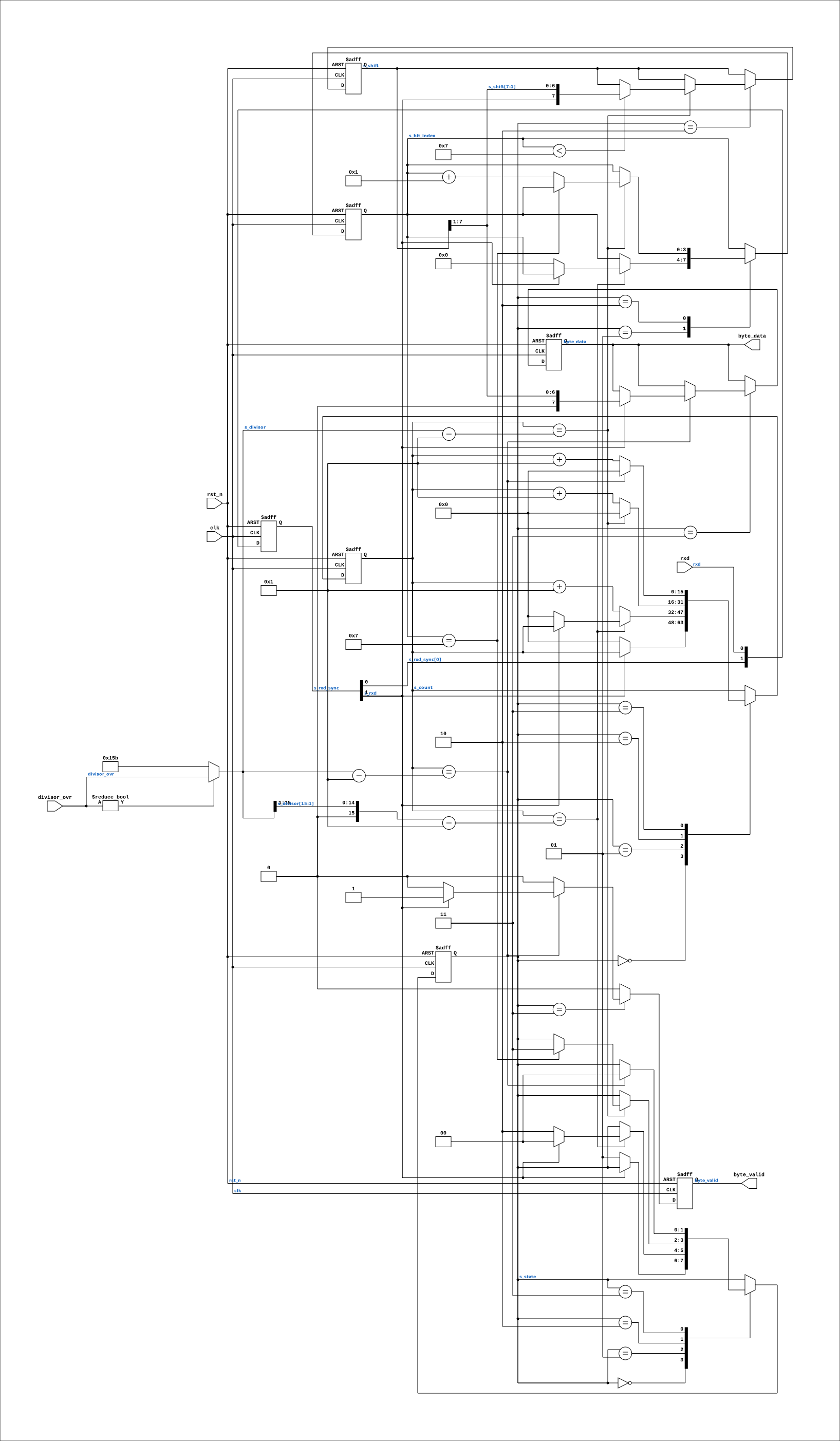
Schematic
Drawn from the Verilog: the yosys netlist of the Nexys 4 DDR build, instance CONSOLE_RX. Sub-modules are boxes (click the picture to open it full size; there every sub-module box links to its page, and every wire shows its Verilog name).
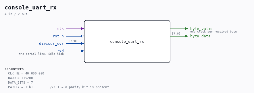
Parameters
| Parameter | Default |
|---|---|
CLK_HZ |
40_000_000 |
BAUD |
115200 |
DATA_BITS |
7 |
PARITY |
1'b1 //! 1 = a parity bit is present |
Ports
| Direction | Width | Name | Description |
|---|---|---|---|
| input | 1 |
clk |
|
| input | 1 |
rst_n (active low) |
|
| input | [15:0] |
divisor_ovr |
|
| input | 1 |
rxd |
the serial line, idle high |
| output | 1 |
byte_valid |
one clock per received byte |
| output | [7:0] |
byte_data |
Verilog source
Verilog/Terminals/rtl/console_uart_rx.v on GitHub.
Show the Verilog of console_uart_rx (168 lines)
//============================================================================
//! Console UART receiver - deserializes the ND-120's console TX line
//!
//! Part of the board-independent terminal core (Verilog/Terminals/).
//!
//! WHY THIS EXISTS. The terminal wants bytes; the machine emits an RS-232 bit
//! stream. The clean thing would be to tap the byte inside the console UART
//! before it is serialized - but that UART is `SC2661_UART` in
//! CPU-BOARD-3202/circuit/IO_UART_42.v, shared RTL used by every board and by
//! the Verilator reference, so adding a port there means re-running the whole
//! unit suite. Deserializing the line costs one small module, touches no
//! shared code, and has the side benefit of exercising the REAL framing.
//!
//! FRAMING IS NOT A CONSTANT. The SC2661 is software programmable - baud and
//! framing are set at run time by the machine, not fixed in RTL. This repo's
//! own console.ps1:17 says the OPCOM console is "7E1 in some configurations;
//! the board check is plain 8N1", and the deployed fast builds run 115200.
//! So the parameters below MUST be set to match whatever the machine is
//! actually programmed to, and getting them wrong shows up immediately as
//! garbage on screen. (The MEGA65 plan's claim of "7E2" is not confirmed
//! anywhere - do not copy that number without checking.)
//!
//! Parity is RECEIVED BUT NOT CHECKED: the bit is consumed so the framing
//! stays aligned, and that is all. A parity error on a console line means one
//! wrong character on screen, which the reader can see; dropping the character
//! instead would hide it.
//!
//! Written 27-AUG-2026.
//============================================================================

`default_nettype none

module console_uart_rx #(
    parameter integer CLK_HZ    = 40_000_000,  //! clock feeding this module
    parameter integer BAUD      = 115200,
    parameter integer DATA_BITS = 7,           //! 7 or 8
    parameter         PARITY    = 1'b1         //! 1 = a parity bit is present
) (
    input wire clk,
    input wire rst_n,

    //! CLOCKS PER BIT, AT RUN TIME. Zero means "use the CLK_HZ/BAUD parameters",
    //! which is what every board did until the Nexys gained a second video mode.
    //!
    //! WHY THIS EXISTS. The console shares one clock domain with the video, so
    //! switching the pixel clock between 800x600 (40 MHz) and 1920x1080 (148.5
    //! MHz) also changes what a bit time is worth. A compile-time divisor would
    //! be right in one mode and produce garbage in the other - and it would look
    //! like a terminal bug rather than a clock bug, which is the expensive kind.
    input wire [15:0] divisor_ovr,

    input wire rxd,  //! the serial line, idle high

    output reg       byte_valid,  //! one clock per received byte
    output reg [7:0] byte_data
);

  localparam integer DIVISOR   = CLK_HZ / BAUD;      //! clocks per bit
  localparam integer HALF_BIT  = DIVISOR / 2;

  wire [15:0] s_divisor  = (divisor_ovr != 16'd0) ? divisor_ovr : DIVISOR[15:0];
  wire [15:0] s_half_bit = {1'b0, s_divisor[15:1]};
  //! data bits + optional parity + the stop bit we wait through
  localparam integer TAIL_BITS = DATA_BITS + (PARITY ? 1 : 0);

  localparam [1:0] ST_IDLE  = 2'd0;
  localparam [1:0] ST_START = 2'd1;
  localparam [1:0] ST_DATA  = 2'd2;
  localparam [1:0] ST_STOP  = 2'd3;

  reg [1:0] s_state;
  reg [15:0] s_count;
  reg [3:0] s_bit_index;
  reg [7:0] s_shift;

  // Two flops against metastability - the line is asynchronous to this clock.
  reg [1:0] s_rxd_sync;
  wire      s_rxd = s_rxd_sync[1];

  always @(posedge clk or negedge rst_n) begin
    if (!rst_n) begin
      s_rxd_sync <= 2'b11;
      s_state    <= ST_IDLE;
      s_count    <= 16'd0;
      s_bit_index<= 4'd0;
      s_shift    <= 8'd0;
      byte_valid <= 1'b0;
      byte_data  <= 8'd0;
    end else begin
      s_rxd_sync <= {s_rxd_sync[0], rxd};
      byte_valid <= 1'b0;

      case (s_state)

        ST_IDLE: begin
          // A falling edge is a start bit - maybe. Wait half a bit and look
          // again, so a glitch on an idle line does not start a character.
          if (!s_rxd) begin
            s_state <= ST_START;
            s_count <= 16'd0;
          end
        end

        ST_START: begin
          if (s_count == s_half_bit - 16'd1) begin
            if (!s_rxd) begin
              // Still low at the middle of the bit: a real start bit.
              s_state     <= ST_DATA;
              s_count     <= 16'd0;
              s_bit_index <= 4'd0;
            end else begin
              s_state <= ST_IDLE;  // it was a glitch
            end
          end else begin
            s_count <= s_count + 16'd1;
          end
        end

        ST_DATA: begin
          // From the middle of the start bit, every DIVISOR clocks lands in
          // the middle of the next bit.
          if (s_count == s_divisor - 16'd1) begin
            s_count <= 16'd0;

            if (s_bit_index < DATA_BITS) begin
              // LSB first.
              s_shift <= {s_rxd, s_shift[7:1]};
            end
            // else: this is the parity bit - consumed, not checked

            if (s_bit_index == TAIL_BITS - 1) begin
              s_state <= ST_STOP;
            end else begin
              s_bit_index <= s_bit_index + 4'd1;
            end
          end else begin
            s_count <= s_count + 16'd1;
          end
        end

        ST_STOP: begin
          if (s_count == s_divisor - 16'd1) begin
            s_count <= 16'd0;
            s_state <= ST_IDLE;
            if (s_rxd) begin
              // Valid stop bit. With 7 data bits the shift register filled
              // from the top, so the byte sits in the high 7 bits - shift it
              // down. This is the step that silently mangles every character
              // if DATA_BITS is set wrong.
              byte_valid <= 1'b1;
              byte_data  <= (DATA_BITS == 8) ? s_shift : {1'b0, s_shift[7:1]};
            end
            // A framing error (stop bit low) drops the character; the line has
            // gone out of sync and the next idle period resynchronizes it.
          end else begin
            s_count <= s_count + 16'd1;
          end
        end

        default: s_state <= ST_IDLE;

      endcase
    end
  end

endmodule

`default_nettype wire