PAL_44402D
Source: Verilog/PAL/PAL_44402D.v
Hierarchy: not instantiated by any of the 9 build tops (elaborated by yosys).
Module hierarchy - All modules
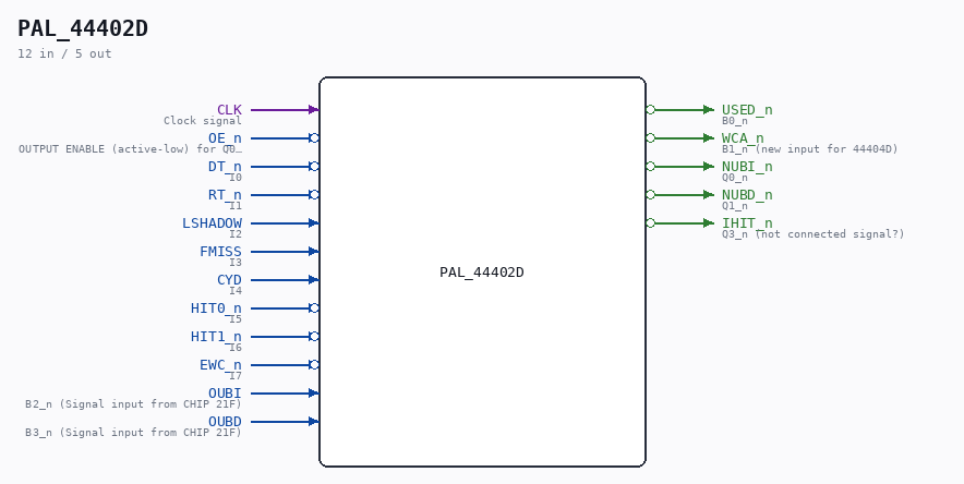
Schematic
Drawn from the Verilog: no build top uses this module, so it was elaborated from its own file with no defines and default parameters. Sub-modules are boxes (click the picture to open it full size; there every sub-module box links to its page, and every wire shows its Verilog name).
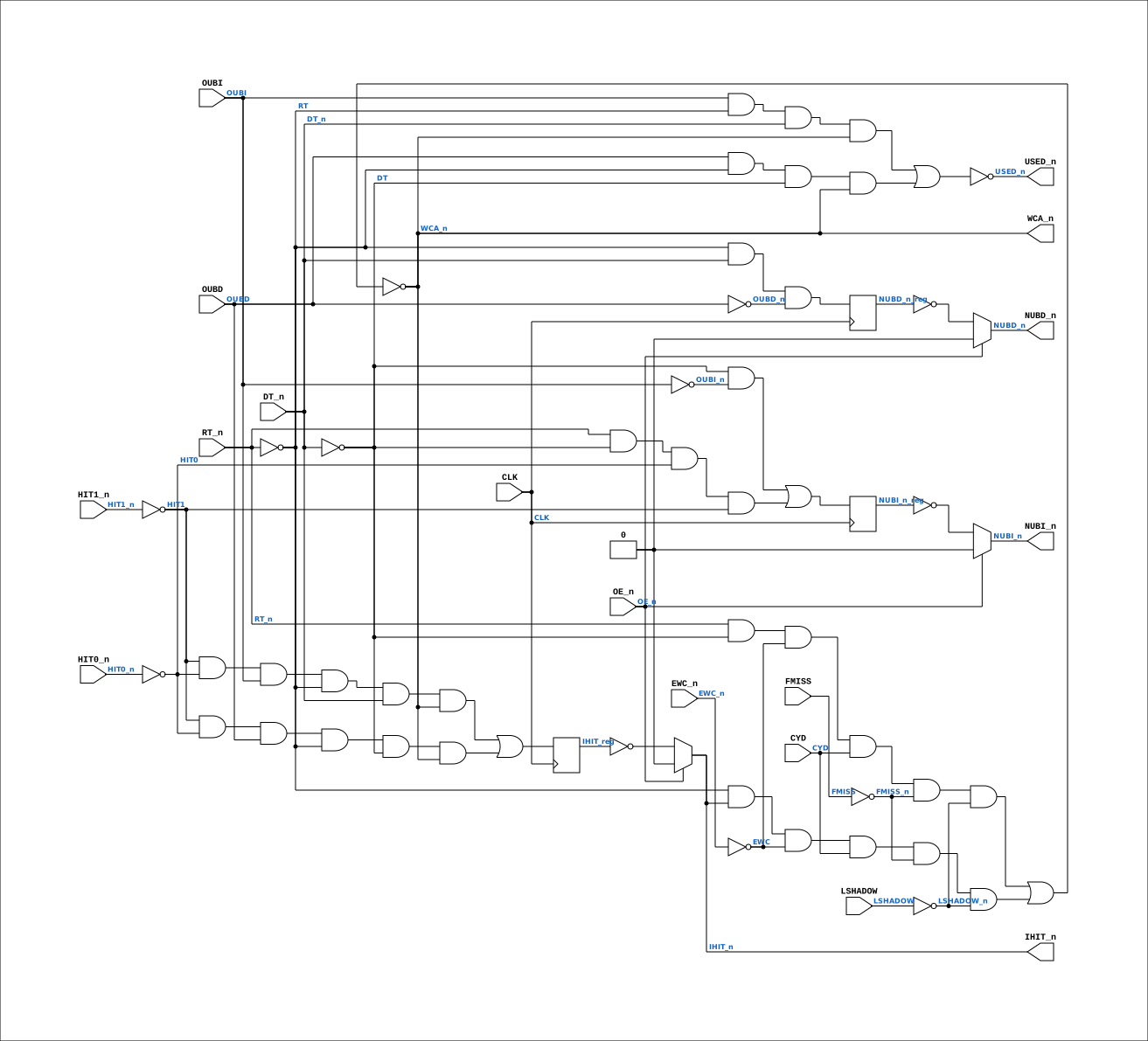
Description
ND120 PALASM CODE CONVERTED TO VERILOG Component PAL 44402D Last reviewed: 2-FEB-2025 Ronny Hansen
Ports
| Direction | Width | Name | Description |
|---|---|---|---|
| input | 1 |
CLK |
Clock signal |
| input | 1 |
OE_n (active low) |
OUTPUT ENABLE (active-low) for Q0-Q3 |
| input | 1 |
DT_n (active low) |
I0 |
| input | 1 |
RT_n (active low) |
I1 |
| input | 1 |
LSHADOW |
I2 |
| input | 1 |
FMISS |
I3 |
| input | 1 |
CYD |
I4 |
| input | 1 |
HIT0_n (active low) |
I5 |
| input | 1 |
HIT1_n (active low) |
I6 |
| input | 1 |
EWC_n (active low) |
I7 |
| output | 1 |
USED_n (active low) |
B0_n |
| output | 1 |
WCA_n (active low) |
B1_n (new input for 44404D) |
| input | 1 |
OUBI |
B2_n (Signal input from CHIP 21F) |
| input | 1 |
OUBD |
B3_n (Signal input from CHIP 21F) |
| output | 1 |
NUBI_n (active low) |
Q0_n |
| output | 1 |
NUBD_n (active low) |
Q1_n |
| output | 1 |
IHIT_n (active low) |
Q3_n (not connected signal?) |
Verilog source
Verilog/PAL/PAL_44402D.v on GitHub.
Show the Verilog of PAL_44402D (128 lines)
/**********************************************************************************************************
** ND120 PALASM CODE CONVERTED TO VERILOG                                                                **
**                                                                                                       **
** Component PAL 44402D                                                                                  **
**                                                                                                       **
** Last reviewed: 2-FEB-2025                                                                             **
** Ronny Hansen                                                                                          **
***********************************************************************************************************/


// PAL16R4
// JLB/CJTC 8AUG86
// 44402D,18F,UBITS


// PCB 3202D sheet 25:
//
// PAL input signal PD2 is connected to PAL OE_n (and PD1 to PD4 is ALWAYS 0/FALSE in the 3202 circuit board)
//     input signal UCLK is connectec to PAL CK pin


// PAL16R4D (https://rocelec.widen.net/view/pdf/c6dwcslffz/VANTS00080-1.pdf)

// I/O 1,2, 7 and 8 (Pins B0 to B3) is not controlled by OE_n, only O3,O4,O5 and O6 (Pin's Q0-Q3)
// NOTE: B0 to B3 is input OR output depending on PALASM code.

// Four D flip-flops controlled by CLK signal (and reads input to flip-flop O3,O4,O5 and O6) when transision from LOW to HIGH.
// O3-O6 output is controlled by OE_n (HIGH signal means output is three-state)


module PAL_44402D (
    input CLK,  //! Clock signal
    input OE_n, //! OUTPUT ENABLE (active-low) for Q0-Q3

    input DT_n,     //! I0
    input RT_n,     //! I1
    input LSHADOW,  //! I2
    input FMISS,    //! I3
    input CYD,      //! I4
    input HIT0_n,   //! I5
    input HIT1_n,   //! I6
    input EWC_n,    //! I7

    output USED_n,  //! B0_n
    output WCA_n,   //! B1_n (new input for 44404D)
    input  OUBI,    //! B2_n (Signal input from CHIP 21F)
    input  OUBD,    //! B3_n (Signal input from CHIP 21F)

    output NUBI_n,  //! Q0_n
    output NUBD_n,  //! Q1_n
                    //! Q2_n (not connected, no signal)
    output IHIT_n   //! Q3_n (not connected signal?)
);

  // CLK and /OE impacts signals:
  //  Q0 = /NUBI, Q1=/NUBD, Q2= n.c., Q3= /IHIT (seems like its not connected to anything)

  // Registers for CLOCKED signals
  reg  NUBI_n_reg;
  reg  NUBD_n_reg;
  reg  IHIT_reg;


  // Creating non-negated wires for active-low inputs
  wire DT = ~DT_n;
  wire HIT0 = ~HIT0_n;
  wire HIT1 = ~HIT1_n;
  wire EWC = ~EWC_n;

  // Creating negated wires for active-high inputs
  wire OUBI_n = ~OUBI;
  wire OUBD_n = ~OUBD;
  wire RT = ~RT_n;
  wire FMISS_n = ~FMISS;
  wire LSHADOW_n = ~LSHADOW;

  // Flip-flop logic for Q0, Q1, Q2 and Q3 (Asyncronous D flip-flop)
  always @(posedge CLK) begin


    // Logic for NUBI_n (Q0 - active-low)
    NUBI_n_reg <= (DT & OUBI_n) |  // READ OR WRITE KEEP OLD VALUE
    (RT_n & DT & HIT0 & HIT1);  // CLEAR IF WRITE WITH HIT

    // Logic for NUBD_n (Q1 - active-low)
    NUBD_n_reg <= (RT & DT_n & OUBD_n);  // IF FETCH KEEP OLD VALUE

    // Logic for IHIT (Q3)
    IHIT_reg <= (HIT1 & HIT0 & OUBI & RT & DT_n & WCA_n) |  // FETCH
    (HIT1 & HIT0 & OUBD & RT & DT & WCA_n);  // READ

  end

  // Output logic for Q0_n, Q1_n, Q2_n

  // PALASM 44402D (verified against the original scan 30-JUL): the pins NUBI
  // and NUBD are ACTIVE-HIGH in the pin list, and the registered equations
  // define /NUBI and /NUBD - a PAL16R4 output inverts the register onto the
  // pin, so pin = ~register. The port names here are historical misnomers:
  // they carry the ACTIVE-HIGH NUBI/NUBD pins straight into the used-bit RAM
  // (CPU_MMU_CACHE_25 chip 21F, non-inverting), whose output returns as the
  // active-high OUBI/OUBD inputs. The missing inversion below broke the
  // used-bit loop (used bits toggled on fetch instead of holding; IHIT/USED
  // computed from inverted state) - 30-JUL PAL audit find.
  // Q0
  assign NUBI_n = OE_n ? 1'b0 : ~NUBI_n_reg;

  // Q1
  assign NUBD_n = OE_n ? 1'b0 : ~NUBD_n_reg;

  // Q3
  assign IHIT_n = OE_n ? 1'b0 : ~IHIT_reg;


  // Logic for USED_n (active-low)
  assign USED_n = ~((OUBI & RT & DT_n & WCA_n) |  // FETCH
      (OUBD & RT & DT & WCA_n)  // READ
      );

  // Logic for WCA_n (active-low)
  assign WCA_n = ~((RT_n & DT & EWC & CYD & FMISS_n & LSHADOW_n) |  // WRITE OUTSIDE SHADOW
      (RT & IHIT_n & EWC & CYD & FMISS_n & LSHADOW_n)  // FETCH/READ WITHOUT HIT OUTSIDE SHADOW
      );


endmodule