BIF_DPATH_PESPEA_13
Source: Verilog/CPU-BOARD-3202/circuit/BIF_DPATH_PESPEA_13.v
Where it sits (Simulation): ND120_TOP > ND120_CORE > ND3202D > BIF_5 > BIF_DPATH_9 > BIF_DPATH_PESPEA_13
- instance path: CORE.CPU_BOARD.BIF.DPATH.PESPEA
Used in: BIF_DPATH_9 (all tops)
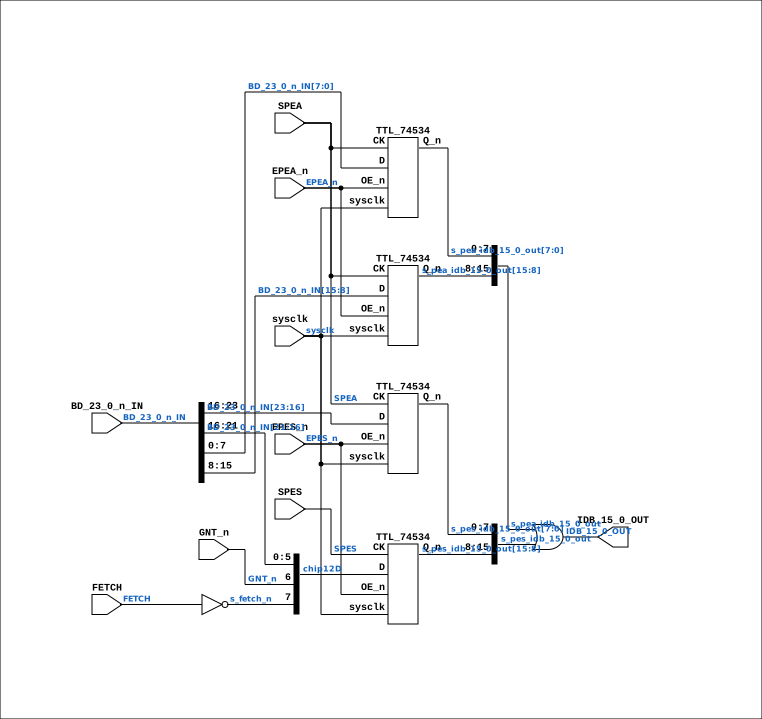
Contains: TTL_74534 x4
Module hierarchy - All modules
Schematic
Drawn from the Verilog: the yosys netlist of the Simulation (Verilator) build, instance CORE.CPU_BOARD.BIF.DPATH.PESPEA. Sub-modules are boxes (click the picture to open it full size; there every sub-module box links to its page, and every wire shows its Verilog name).
Description
ND120 CPU, MM&M BIF/DPATH/PESPEA BIF PES & PEA SHEET 13 of 50 Last reviewed: 13-MAY-2024 Ronny Hansen
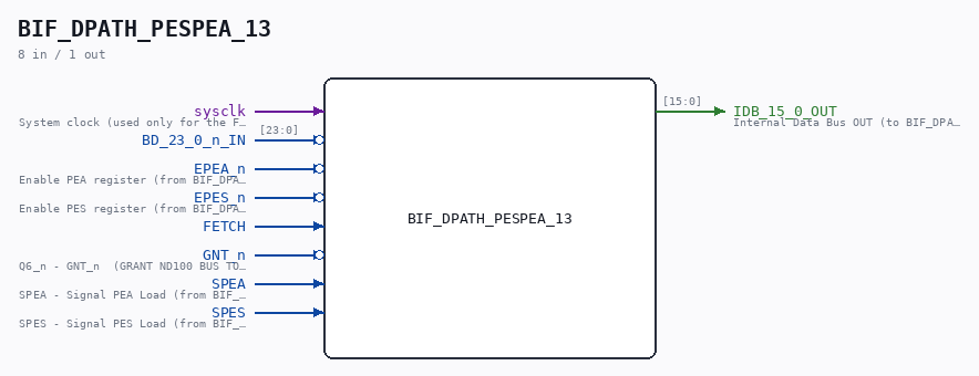
Ports
| Direction | Width | Name | Description |
|---|---|---|---|
| input | 1 |
sysclk |
System clock (used only for the FF-mode strobe edge-capture) |
| input | [23:0] |
BD_23_0_n_IN |
|
| input | 1 |
EPEA_n (active low) |
Enable PEA register (from BIF_DPATH_9.EPEA_n) |
| input | 1 |
EPES_n (active low) |
Enable PES register (from BIF_DPATH_9.EPES_n) |
| input | 1 |
FETCH |
|
| input | 1 |
GNT_n (active low) |
Q6_n - GNT_n (GRANT ND100 BUS TO A DMA DEVICE OR EXTERNAL BUS CONTROLLER) (from PAL_44801A.GNT_n) |
| input | 1 |
SPEA |
SPEA - Signal PEA Load (from BIF_DPATH_9.SPEA) |
| input | 1 |
SPES |
SPES - Signal PES Load (from BIF_DPATH_9.SPES) |
| output | [15:0] |
IDB_15_0_OUT |
Internal Data Bus OUT (to BIF_DPATH_9.IDB_15_0_OUT) |
Verilog source
Verilog/CPU-BOARD-3202/circuit/BIF_DPATH_PESPEA_13.v on GitHub.
Show the Verilog of BIF_DPATH_PESPEA_13 (137 lines)
/**************************************************************************
** ND120 CPU, MM&M                                                       **
** BIF/DPATH/PESPEA                                                      **
** BIF PES & PEA                                                         **
** SHEET 13 of 50                                                        **
**                                                                       **
** Last reviewed: 13-MAY-2024                                            **
** Ronny Hansen                                                          **
***************************************************************************/

module BIF_DPATH_PESPEA_13 (
    input        sysclk,  //! System clock (used only for the FF-mode strobe edge-capture)
    input [23:0] BD_23_0_n_IN,
    input        EPEA_n,  //! Enable PEA register (from BIF_DPATH_9.EPEA_n)
    input        EPES_n,  //! Enable PES register (from BIF_DPATH_9.EPES_n)
    input        FETCH,
    input        GNT_n,   //! Q6_n - GNT_n  (GRANT ND100 BUS TO A DMA DEVICE OR EXTERNAL BUS CONTROLLER) (from PAL_44801A.GNT_n)
    input        SPEA,    //! SPEA - Signal PEA Load (from BIF_DPATH_9.SPEA)
    input        SPES,    //! SPES - Signal PES Load (from BIF_DPATH_9.SPES)

    output [15:0] IDB_15_0_OUT  //! Internal Data Bus OUT (to BIF_DPATH_9.IDB_15_0_OUT)
);


  /*******************************************************************************
   ** The wires are defined here                                                 **
   *******************************************************************************/
  wire [23:0] s_bd_23_0_n_in;
  wire [15:0] s_idb_15_0_out;

  wire [15:0] s_pea_idb_15_0_out;
  wire [15:0] s_pes_idb_15_0_out;


  wire [ 7:0] chip12D;

  wire        s_epea_n;
  wire        s_epes_n;
  wire        s_spea;
  wire        s_spes;
  wire        s_gnt_n;
  wire        s_fetch_n;

  /*******************************************************************************
   ** Here all input connections are defined                                     **
   *******************************************************************************/
  assign s_bd_23_0_n_in[23:0] = BD_23_0_n_IN[23:0];
  assign s_epea_n             = EPEA_n;
  assign s_epes_n             = EPES_n;
  assign s_spea               = SPEA;
  assign s_spes               = SPES;
  assign s_gnt_n              = GNT_n;
  assign s_fetch_n            = ~FETCH;

  /*******************************************************************************
   ** Here all output connections are defined                                    **
   *******************************************************************************/
  assign IDB_15_0_OUT         = s_idb_15_0_out[15:0];

  /*******************************************************************************
   ** Here all sub-circuits are defined                                          **
   *******************************************************************************/

  // Read PEA register
  //  PEA (Parity Error Address).  The PEA register is a 16-bit register that contains the address of the last byte that caused a parity error.  The
  //  PEA register is loaded with the address of the last byte that caused a parity error when the parity error is detected.


  assign s_idb_15_0_out       = s_pea_idb_15_0_out | s_pes_idb_15_0_out;

  // P3 (docs/plan-fix-unconstrained-clocks.md): SPEA/SPES are parity-error
  // capture strobes, not clocks. In FF mode the registers capture on a
  // sysclk-detected strobe rise instead of clocking on the routed net.
`ifdef FPGA_FF_MODE
  localparam SPE_CAPTURE = 2;
`else
  localparam SPE_CAPTURE = 0;
`endif

  TTL_74534 #(.USE_SYSCLK(SPE_CAPTURE)) CHIP_9A (
      .sysclk(sysclk),
      .CK(s_spea),
      .OE_n(s_epea_n),
      .D(s_bd_23_0_n_in[15:8]),
      .Q_n(s_pea_idb_15_0_out[15:8])
  );


  TTL_74534 #(.USE_SYSCLK(SPE_CAPTURE)) CHIP_8A (
      .sysclk(sysclk),
      .CK(s_spea),
      .OE_n(s_epea_n),
      .D(s_bd_23_0_n_in[7:0]),
      .Q_n(s_pea_idb_15_0_out[7:0])
  );


  assign chip12D[7]   = s_fetch_n;
  assign chip12D[6]   = s_gnt_n;
  assign chip12D[5:0] = s_bd_23_0_n_in[21:16];

  /// Read PES register
  /// PES (Parity Error Status). The PES register is a 16-bit register that contains the status of the last parity error detected.
  ///
  /// +-----+---+-----+------------+--------------------------------------------+
  /// |  15 | 14| 13  | 12  -    8 |     7                 -               0    |
  /// +-----+---+-----+---------------------------------------------------------+
  /// |FETCH|DMA|FATAL| Error code | Upper 8 bits of physical addr (LBD23-LBD16 |
  /// +-----+---+-----+------------+--------------------------------------------+
  ///
  /// Bits 0-7: Most significant address bits of the last memory reference.
  /// Bits 8-12: Error code(0-4) which points out the failing and corrected bit if a single bit error has occurred(see bit 13). Refer to the table 11 and 12 in "ND-06026-1-EN ND-110 Functional Description.pdf"
  /// Bit 13: FATAL - If fatal is set 1, a multiple error has occurred and the error code does not contain relevant information.Fatal not set ('0') means single bit error (bit number found in error code) or good data(error code = 0).
  /// Bit 14: DMA   - Error occurred during DMA reference.
  /// Bit 15: FETCH — Error occurred during instruction fetch or during an examine (EXAM) or a deposit(DEP) instruction.
  ///

  TTL_74534 #(.USE_SYSCLK(SPE_CAPTURE)) CHIP_12A (
      .sysclk(sysclk),
      .CK(s_spes),
      .OE_n(s_epes_n),
      .D(chip12D[7:0]),
      .Q_n(s_pes_idb_15_0_out[15:8])
  );

  TTL_74534 #(.USE_SYSCLK(SPE_CAPTURE)) CHIP_10A (
      .sysclk(sysclk),
      .CK(s_spea),
      .OE_n(s_epes_n),
      .D(s_bd_23_0_n_in[23:16]),
      .Q_n(s_pes_idb_15_0_out[7:0])
  );

endmodule