SevenSegDebug
Source: Verilog/Shared/support/SevenSegDebug.v
Where it sits (Basys3): ND120_TOP > SevenSegDebug
- instance path: SEVEN_SEG
Used in: ND120_TOP (Basys3, Cmod)
Contains: no other modules.
Module hierarchy - All modules
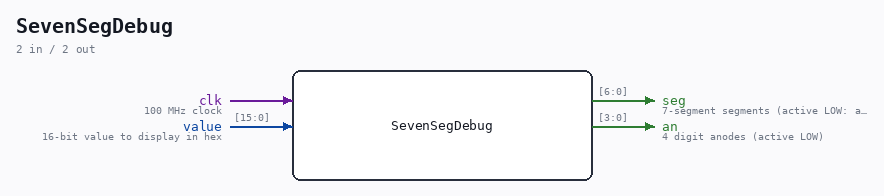
Schematic
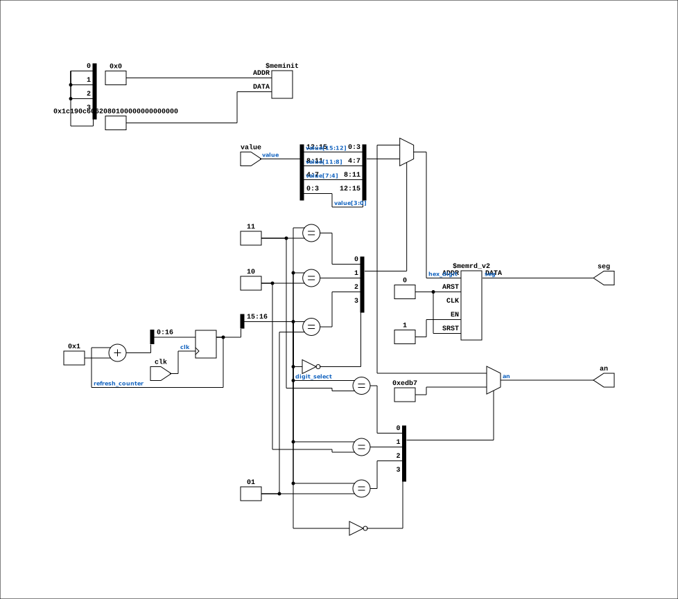
Drawn from the Verilog: the yosys netlist of the Basys3 build, instance SEVEN_SEG. Sub-modules are boxes (click the picture to open it full size; there every sub-module box links to its page, and every wire shows its Verilog name).
Description
7-Segment Display Debug Module for Basys3 Displays a 16-bit value on the 4-digit 7-segment display. Multiplexes between digits at ~1 KHz refresh rate. Basys3 7-seg: active LOW segments, active LOW digit anodes Accent: Accent bit (h/H) at 4th bit of digit_select -> dot Last reviewed: 30-MAR-2026 Ronny Hansen
Ports
| Direction | Width | Name | Description |
|---|---|---|---|
| input | 1 |
clk |
100 MHz clock |
| input | [15:0] |
value |
16-bit value to display in hex |
| output | [6:0] |
seg |
7-segment segments (active LOW: a,b,c,d,e,f,g) |
| output | [3:0] |
an |
4 digit anodes (active LOW) |
Verilog source
Verilog/Shared/support/SevenSegDebug.v on GitHub.
Show the Verilog of SevenSegDebug (67 lines)
/**************************************************************************
** 7-Segment Display Debug Module for Basys3                            **
**                                                                       **
** Displays a 16-bit value on the 4-digit 7-segment display.            **
** Multiplexes between digits at ~1 KHz refresh rate.                   **
**                                                                       **
** Basys3 7-seg: active LOW segments, active LOW digit anodes            **
** Accent: Accent bit (h/H) at 4th bit of digit_select -> dot            **
**                                                                       **
** Last reviewed: 30-MAR-2026                                            **
** Ronny Hansen                                                          **
***************************************************************************/

module SevenSegDebug (
    input wire clk,             // 100 MHz clock
    input wire [15:0] value,    // 16-bit value to display in hex

    output reg [6:0] seg,       // 7-segment segments (active LOW: a,b,c,d,e,f,g)
    output reg [3:0] an         // 4 digit anodes (active LOW)
);

  // Clock divider for ~1 KHz multiplex refresh
  // 100 MHz / 2^17 = ~763 Hz
  reg [16:0] refresh_counter = 0;
  wire [1:0] digit_select;

  always @(posedge clk)
    refresh_counter <= refresh_counter + 1;

  assign digit_select = refresh_counter[16:15];

  // Select which digit to display
  reg [3:0] hex_digit;

  always @(*) begin
    case (digit_select)
      2'b00: begin an = 4'b1110; hex_digit = value[3:0];   end  // Rightmost
      2'b01: begin an = 4'b1101; hex_digit = value[7:4];   end
      2'b10: begin an = 4'b1011; hex_digit = value[11:8];  end
      2'b11: begin an = 4'b0111; hex_digit = value[15:12]; end
    endcase
  end

  // Hex to 7-segment decoder (active LOW: 0=ON)
  //   segment encoding: seg[6:0] = gfedcba
  always @(*) begin
    case (hex_digit)
      4'h0: seg = 7'b1000000;  // 0
      4'h1: seg = 7'b1111001;  // 1
      4'h2: seg = 7'b0100100;  // 2
      4'h3: seg = 7'b0110000;  // 3
      4'h4: seg = 7'b0011001;  // 4
      4'h5: seg = 7'b0010010;  // 5
      4'h6: seg = 7'b0000010;  // 6
      4'h7: seg = 7'b1111000;  // 7
      4'h8: seg = 7'b0000000;  // 8
      4'h9: seg = 7'b0010000;  // 9
      4'hA: seg = 7'b0001000;  // A
      4'hB: seg = 7'b0000011;  // b
      4'hC: seg = 7'b1000110;  // C
      4'hD: seg = 7'b0100001;  // d
      4'hE: seg = 7'b0000110;  // E
      4'hF: seg = 7'b0001110;  // F
    endcase
  end

endmodule