AM29C821
Source: Verilog/Shared/support/AM29C821.v
Where it sits (Simulation): ND120_TOP > ND120_CORE > ND3202D > MEM_43 > MEM_ADDR_44 > AM29C821
- instance path: CORE.CPU_BOARD.MEM.ADDR.CHIP_3H_ROW_ADDRESS
Used in: BIF_BCTL_SYNC_8 (all tops), IO_UART_42 (all tops), MEM_ADDR_44 (all tops), MEM_LBDIF_48 (all tops)
Contains: no other modules.
Module hierarchy - All modules
Schematic
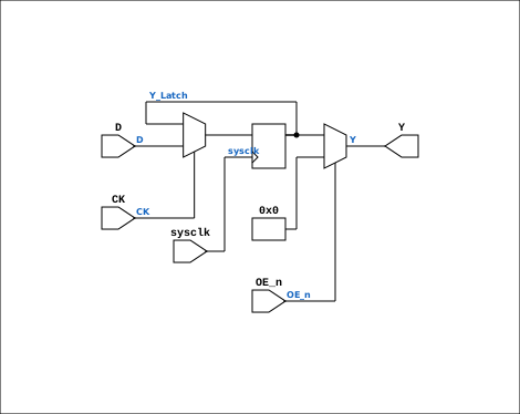
Drawn from the Verilog: the yosys netlist of the Simulation (Verilator) build, instance CORE.CPU_BOARD.IO.UART.CHIP_33G. Sub-modules are boxes (click the picture to open it full size; there every sub-module box links to its page, and every wire shows its Verilog name).
Description
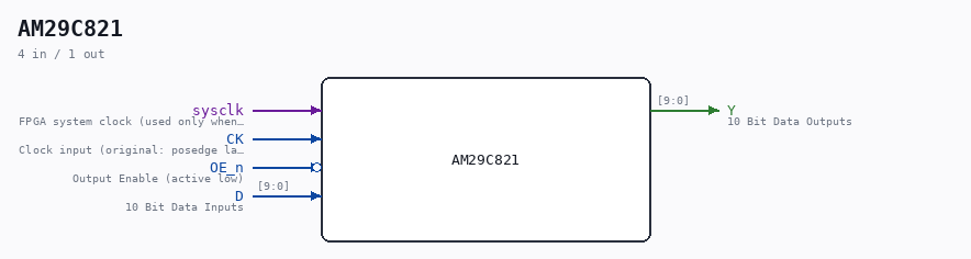
ND120 CPU AM29C821 Bus Driver 10 bits. Positive edge-triggered registers with D-type flip-flops and 3-state Documentation: https://www.digikey.com/en/products/detail/rochester-electronics-llc/AM29C821-BLA/12095382 Last reviewed: 11-NOV-2024 Ronny Hansen
Ports
| Direction | Width | Name | Description |
|---|---|---|---|
| input | 1 |
sysclk |
FPGA system clock (used only when USE_SYSCLK=1) |
| input | 1 |
CK |
Clock input (original: posedge latch) |
| input | 1 |
OE_n (active low) |
Output Enable (active low) |
| input | [9:0] |
D |
10 Bit Data Inputs |
| output | [9:0] |
Y |
10 Bit Data Outputs |
Verilog source
Verilog/Shared/support/AM29C821.v on GitHub.
Show the Verilog of AM29C821 (62 lines)
/**************************************************************************************************
** ND120 CPU                                                                                     **
**                                                                                               **
** AM29C821                                                                                      **
**                                                                                               **
** Bus Driver 10 bits.                                                                           **
** Positive edge-triggered registers with D-type flip-flops and 3-state                          **
**                                                                                               **
** Documentation:                                                                                **
** https://www.digikey.com/en/products/detail/rochester-electronics-llc/AM29C821-BLA/12095382    **
**                                                                                               **
** Last reviewed: 11-NOV-2024                                                                    **
** Ronny Hansen                                                                                  **
***************************************************************************************************/

module AM29C821 (
    input  wire       sysclk, //! FPGA system clock (used only when USE_SYSCLK=1)
    input  wire       CK,     //! Clock input (original: posedge latch)
    input  wire       OE_n,   //! Output Enable (active low)
    input  wire [9:0] D,      //! 10 Bit Data Inputs
    output wire [9:0] Y       //! 10 Bit Data Outputs
);

  // USE_SYSCLK=0 (default): original posedge CK — correct for real clock
  //   signals like s_osc.
  // USE_SYSCLK=1: level-sensitive sysclk capture — ONLY correct when CK is a
  //   1-sysclk-wide pulse (e.g., s_clk = ~TERM_n). With a multi-cycle CK the
  //   register keeps re-capturing D every sysclk while CK is high — NOT
  //   edge-triggered semantics. (This is what broke the memory write path
  //   when used for the BCGNT50 address latches: LBD had moved on from the
  //   address to the write data by the end of the grant window.)
  // USE_SYSCLK=2: sysclk-sampled RISING-EDGE capture — the FPGA-safe
  //   replacement for posedge-CK when CK is a multi-cycle control signal
  //   (e.g., BCGNT50): captures D exactly once per CK rise, no clock net.
  parameter USE_SYSCLK = 0;

  reg [9:0] Y_Latch = 10'b0;

  generate
    if (USE_SYSCLK == 1) begin : gen_sysclk
      always @(posedge sysclk) begin
        if (CK) Y_Latch <= D;
      end
    end else if (USE_SYSCLK == 2) begin : gen_sysclk_edge
      reg ck_d = 1'b0;
      always @(posedge sysclk) begin
        ck_d <= CK;
        if (CK && !ck_d) Y_Latch <= D;
      end
    end else begin : gen_posedge_ck
      always @(posedge CK) begin
        Y_Latch <= D;
      end
    end
  endgenerate

  // Output control
  // When OE_n is low (active), outputs reflect the registered data
  // When OE_n is high, outputs are zero (tri-state equivalent)
  assign Y = (OE_n == 1'b0) ? Y_Latch : 10'b0;

endmodule