TTL_74244
Source: Verilog/Shared/support/TTL_74244.v
Where it sits (Simulation): ND120_TOP > ND120_CORE > ND3202D > IO_37 > IO_REG_41 > TTL_74244
- instance path: CORE.CPU_BOARD.IO.REG_MODULE.CHIP_27A_STRAP
Used in: IO_PANCAL_40 (all tops), IO_REG_41 (all tops)
Contains: no other modules.
Module hierarchy - All modules
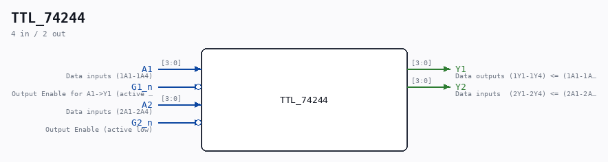
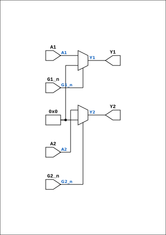
Schematic
Drawn from the Verilog: the yosys netlist of the Simulation (Verilator) build, instance CORE.CPU_BOARD.IO.REG_MODULE.CHIP_27A_STRAP. Sub-modules are boxes (click the picture to open it full size; there every sub-module box links to its page, and every wire shows its Verilog name).
Ports
| Direction | Width | Name | Description |
|---|---|---|---|
| input | [3:0] |
A1 |
Data inputs (1A1-1A4) |
| input | 1 |
G1_n (active low) |
Output Enable for A1->Y1 (active low) |
| output | [3:0] |
Y1 |
Data outputs (1Y1-1Y4) <= (1A1-1A4) |
| input | [3:0] |
A2 |
Data inputs (2A1-2A4) |
| input | 1 |
G2_n (active low) |
Output Enable (active low) |
| output | [3:0] |
Y2 |
Data inputs (2Y1-2Y4) <= (2A1-2A4) |
Verilog source
Verilog/Shared/support/TTL_74244.v on GitHub.
Show the Verilog of TTL_74244 (28 lines)
// 74LS244 (NONE negated outputs)
// Octal Buffers and Line Drivers With 3-State Outputs
// Documentation: https://www.ti.com/lit/ds/symlink/sn74ls244.pdf
//                https://pdf1.alldatasheet.com/datasheet-pdf/view/51057/FAIRCHILD/74244.html

/*
This device is organized as two 4-bit buffers and drivers with separate output-enable (G) inputs.
* When G is low, the device passes data from the A inputs to the Y outputs.
* When G is high, the outputs are in the high impedance state.
*/

module TTL_74244(
               input wire [3:0] A1,   // Data inputs (1A1-1A4)
               input wire G1_n,       // Output Enable for A1->Y1 (active low)
               output wire [3:0] Y1,  // Data outputs (1Y1-1Y4) <= (1A1-1A4)


               input wire [3:0] A2,   // Data inputs (2A1-2A4)
               input wire G2_n,       // Output Enable (active low)
               output wire [3:0] Y2   // Data inputs  (2Y1-2Y4) <= (2A1-2A4)
);

assign Y1 = G1_n ? 4'b0 : A1; // If G1_n is high, output is high-impedance
assign Y2 = G2_n ? 4'b0 : A2; // If G2_n is high, output is high-impedance


endmodule